by John Kendall
Our branchline station is called Patchwick. I already described the main station building and platform. This should be a fairly straightforward project - a scratchbuild of the parcels office that goes near the main building.
C&L do a laser cut wood kit of the building (http://www.finescale.org.uk/index.php?option=com_virtuemart&Itemid=55#i), but I thought I could make this from plastic almost as easily.
First order of business was to draw a sketch of the building to scale:
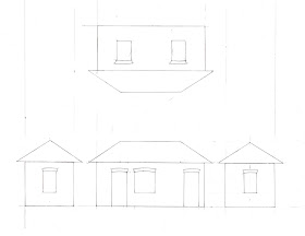
Before starting, I find it a good idea to source the windows and doors. That way the window and door openings can be cut accurately. For something like this, the windows especially are a challenge.
Windows:
My approach was to start with 0.020" plastic card. I measured the apertures (I had wanted to cut the individual panes but I'm not that good) and cut them out. I first glued two strips of 0.020" x 0.040" as horizontals. When dry, I glued a strip on top for the vertical. I added smaller strips across and on top of the horizontals so they were flush with verticals. These were allowed to dry thoroughly and then the backs were rubbed on a file to remove most of the first horizontal strips. I want the backs to be nearly flat to take the glazing. I also scribed a representation of the window frames.
Doors:
Again, starting with 0.020" plastic card, I carefully marked out the doors and removed the inset panes. This was a lesson learned from constructing the main building. I can paint the main door chocolate and a separate inside panel cream. When glued together, the inner panes will be crisp.
These were laborious, but absent anything commercially available, I think they will serve.
Next, I marked out and cut a sheet of 0.040" plastic card for the door and window openings:
The windows and doors will have to be widened by 0.5mm on either side to allow for the brick detail.
I have painted the windows and doors:
The doors are in 2 layers as I described earlier.
I have glued the brick sheet to the walls. At this stage I haven't cut the openings. Before I do that I glued strips to the sides of the openings:
The picture is of the two side walls. The picture on the left is the back of the wall, that on right is the front.
1 April 2012
Today, I cut out the door and window openings:
I show the front and abck of the walls. Features to note are the representation of brick in the door and window openings and bevels on the walls.
The walls after priming:
I used automotive red oxide primer. The tin says it is formulated for car plastics and I have used it for along time.
There is a 0.060" x 0.060" strip across the top of the wall. I will hang the gutters off this.
A strip of brick (glued to 0.020" plastic card) 6 courses wide is on the bottom.
I spent quite some time with the bevels, these need to be very good so that the corners line up.
I painted a coat of acrylic Aged Concrete on the walls this morning. I should have left it about an hour but left it longer.
I used IPA and Qtips to remove the surface paint leaving the concrete colour in the crevices.
2 April 2012
Another thing I learned from Mr. Rice (a very useful chap) is that older walls do not have uniform colour bricks. There are various shades of brown and even black. Yesterday, I went to the art supply store and hasd a look round (I recommend you do this - these places can have very useful things for us modellers). I picked up some fine point coloured pens (light brown, brown and black) and picked out bricks at random to try to represent an older wall.
Very pleasing effect I think.
The final things for the walls are a dusting of rust coloured weathering powder and a coat of matte varnish.
The effect isn't obvious but I think the powder tones everything down and adds yet another layer of shade.
4 April 2012
Finally! Some assembly has been done. In these models as with other jobs, preparation takes quite a lot of time.
Now, a word about the arches above the windows and doors. I gave this some thought and know from experience that simply trying to scribe and cut these from sheet is trying. My approach came down to the following:
1) Start with 0.020" plastic card
2) Draw radii on the card
3) Use my NWSL Chopper to cut 2.5mm lengths from a 0.020 x 0.0156" strip.
4) Glue these to the pattern I wanted.
5) Cut out, file and sand to shape and paint grimy black
For door handles, I simply bent some 0.020" brass wire and glued into a drilled hole in the door.
Window sills are 0.060" x 0.060" strip painted aged concrete.
After assembly, I sprayed with dullcote to cover up any glue marks.
It's time now to consider the roof. I made some formers from 0.040" plastic card. These are based on the scale drawing I made earlier. I deducted 1mm to allow for the roof thickness. I assembled the roof framework as shown:
There was some trial and error here and it's not pretty. Hopefully it will serve.
I plan to glue paper tiles left over from the station building. PVA doesn't work well on plastic so I glued some paper to 0.015" plastic card using spray adhesive (not spray mount!).
Again, there was trial and error and I have trimmed these slightly.
If desired, you can use Wills roof tile sheet or your own preferred method.
I assembled the roof with the paper coated panels, plastic inside, glued to the structure. Edges were sanded smooth. I also added gutters:
Gutters are made from 0.080" half round and 0.015" x 0.156" strip.
5 April 2012
I finished adding the tiles and ridgetiles this morning.
This is a job that takes a bit of time. If you try to do too much, the glue will make a soggy mess. I put some PVA into a mixing jar and used a small flat brush to apply the glue. I put on strips starting from the bottom and alternating the points to give a diamond pattern. Make the strips slightly longer than needed. Lay on two strips each side and leave it for about 15 mins. The glue dries very quickly. Once the long sides are complete and after the glue is dry, trim the strips and sand. Apply the strips to the ends and finally add the ridge tiles.
7 Apr 2012
Yesterday, I installed the glazing. Nothing special here, just try not to get glue on the glass.
Well, it's finished!
I painted the roof starting with red oxide primer, followed by brick red for the tiles and brown for the gutters.
I then carefully checked the position of the downspouts and drilled holes in the gutters. Start with a 0.020" drill through the underside so that the hole can be centered. Increase the drill size and redrill. Check the hole size with the rod you intend to use. The rod I used is 3/64" - it's a personal choice though.
I used my downspout method detailed in an earlier post. I made 4 small blocks with 0.020" holes drilled at 3/64" apart, using the rod as a jig. 0.040" x .156" strip was used and I find it easier to drill the holes before detaching the block from the strip. It's also a good idea to draw a line across the strip. For some reason, I can't seem to drill two holes in a line freehand. Expect to have some rejects - I did.
Draw a faint pencil line down the wall in line with the gutter holes drilled previously. I marked a point 6mm down from the top of the wall and again 24mm below that. This is not a rule, just what I did. (Although I did read that gutter pipes are 6 ft long, so that is likely where they would be secured.)
Put a small dab of superglue over the points marked and place blocks on them trying to keep them centered. Allow the glue to set thoroughly. When dry, carefully paint them the colour of your choice, I chose brown.
Bend the rod to shape so that the straight section sits flat on the wall and final bend sits comfortably in the hole in the gutter. This may take a bit of practice.
Paint the downspount off the model. I primed with Floquil Zinc Chromate, but I'm not of the availability (There's also a Floquil Grey Primer). This is useful for small jobs. Final colour was brown.
Now, with a 0.020" drill, drill the blocks through the wall. Prepare lengths of 0.020" brass wire bent to shape using the 3/64" rod as a jig. Place the downspout in position and insert the bent wire through the holes. Use superglue to secure from the back. Touch up the bare brass with primer and brown paint.
I prepared an inset, 0.020" deep, in the platform to receive this building. I cut a piece of 0.020" plastic card to shape and glued to the bottom of the building. Buildings need to look as though they are integral with the scene, not just plonked. Touch up the edges.
I also touched up the corners by drybrushing some brick colour.
I will weather the building next.
Saturday, March 31, 2012
Sunday, March 25, 2012
Creating a Custom Station Platform
by John Kendall
25 March 2012
This morning I was able to gain access to the track on our branchline to begin making the platform. I always prefer to make my own platforms, using plastic.
Here's one I made earlier:
I thought I'd begin with the very basic first steps to help those who were wondering where to begin.
This method assumes the track has already been laid - our track plans are always curved.
I get myself some light card, don't know the weight but it's about 0.5mm thick. Use a pair of scissors to very roughly cut the card so that its edge overhangs the track by a healthy amount. Find a datum, like a backscene board and press the card over the rail that is next to the platform wall, this will provide a mark. Cut the card at the mark and check the card on the track. The edge of the card should fit snugly to the outer face of the rail. If there are places where it doesn't, trim until it does.
Next, obtain the longest coach that will be used in the station and a pencil. This is a time honoured method. Hold the pencil against the coach side and mark the card as the coach is pushed along the track. Again, cut the card on the mark you just made. Check it again, re-mark and trim until you're happy.
When you're finished you should have something like this:
29 March 2012
My chosen method for constructing this platform is for 2 layers of 0.020" plastic sheet. The first layer is the base layer and the second will be scribed with paving stone detail. A recess is left so that the station building looks like it is part of the platform (not plonked on top). You could use Wills sheet for this but I dislike their small size (hard to disguise the join) and they are difficult to cut.
OK, my first attempt didn't work as well as I wanted. I discovered that the curve was discontinuous in one spot so last night I retraced the line and made the repairs. Today I scribed the paving stones using an Olfa carpet cutter (aka scrawker). Mine is pictured. Also in the picture is an Olfa circle cutter which I used to mark out the edge pavers.
I added strips of 0.040" x 0.100" plastic under the platform edge. This makes the edge crisper and provides something to glue the walls against so I get a consistent inset.
30 March 2012
I finished constructing the platform support walls this morning:
Being white plastic, it's a little difficult to see clearly.
process is as follows:
1) Determine the height above baseboard. According to Rice, height above RAIL is between 3' and 3' 6", or between 12mm and 14mm. However, track height (code 100) is 4mm so add that to get between 16mm and 18mm.
My platform is to be 16mm above baseboard. If this proves to be too low I can always shim up.
2) Cut strips of 0.040" plastic card (I use Evergreen but Slaters is fine too) to, in my case 15mm (the platform top is 0.040" or 1mm thick). These will be 12" long.
3) Cut strips of textured plastic sheet to something a bit wider than 15mm (trim later). I used Finecast English Bond. Slaters do a good selection of brick and stone. This sheet is ~ 0.020" thick and is VERY easy to work with. Glue to the card strips, staggering the joins for strength.
4) I wanted (OK I was told) the top courses to extend from the platform in an inverted step fashion.
a) Cut strips of 0.020" plastic 5mm wide.
b) Cut strips of brick, 3 courses wide. (recall the 0.040" strip under the edge, we want two courses to be revealed).
c) Glue the strips together, making sure that courses line up. Again stagger ends. When dry, trim.
d) For the 2 course layer, I glued fairly wide strips of plastic and brick together. Trim to get a nice edge. Use your knife and steel rule to follow the mortar line. Make as many srips as required.
Now we pause to think about end ramps. These are 1 in 6 minimum. I calculated the length I would need and cut them off from the platform top. Knowing the length of the long side of the triangle and the height, the base is easy to get (I simply drew a picture, but if you want to be clever you could use trig.).
Cut the platform support walls at their ends to the appropriate dimension for the ramp.
Now, glue the 3 course strip to the platform wall, overhanging the ramp. I won't put the protruding bricks along the side of the ramp (doesn't make sense to me). Trim the strip to the ramp angle.
Now, glue the 2 course strip in place and trim to the ramp angle again.
31 March 2012
Having made the main components, I also made some plain walls to support the unseen side of the platform. With these done, I glued it all together as you can see here:
and here:
To ensure the side walls are square I made a bunch of plastic triangles to use a buttresses. I also added widthwise and lengthwise strengthers.
Here's the underside of the platform:
Next - the paint shop.
I primed the platform with red oxide and grey:
It looks massively better now.
I painted the platform wall with acrylic Aged Concrete (any similar colour will do) as the mortar:
Next, I will rub the surface colour off, leaving the mortar in the cracks.
I'm quite pleased with this. I dipped Qtips in IPA and rubbed the surface paint off.
2 April 2012
This morning I started by dry brushing a brick colour (and this is quite subjective, I simply added Tamiya flat red to flat brown) onto the platform support walls. This brightens up the brickwork and adds another layer of shading I think.
Another thing I learned from Mr. Rice (a very useful chap) is that older walls do not have uniform colour bricks. There are various shades of brown and even black. Yesterday, I went to the art supply store and hasd a look round (I recommend you do this - these places can have very useful things for us modellers). I picked up some fine point coloured pens (light brown, brown and black) and picked out bricks at random to try to represent an older wall.
I'm really quite pleased with the way this looks.
I spent some time today making station nameboards:
The name is made with Powerpoint. The board is made from 0.015" paper coated plastic card. Strips of 0.040" x 0.040" were superglued around the edges. The legs are bullhead rail soldered to scrap brass strip.
5 April 2012
Since my last report I completed a number of tasks:
1) Laid down masking tape in the recess for the cinders and trimmed. Also mask the support wall.
1) Painted the platform surface grimy black. I used an airbrush for this.
2) Added the cinders. To prevent cinders and PVA from getting onto the platform top I masked the recesses off. I then brushed on some neat PVA. This was followed by sprinkling fine cinder ballast into the recess. Finish off by spraying some "wet water"* on. This will "lift" the glue and make sure the ballast is soaked.
*Wet water is water mixed with a small amount of soap to break the surface tension. I have read that some people use IPA instead of soap.
Remove the masking tape BEFORE the PVA dries. Leave overnight.
3) This morning I masked the edge of the platform and sprayed on some flat white.
Result:
I don't recommend that you try to brush the white on. In my experience, brushed on paint always bleeds under the tape. If you do, paint a coat of platform colour over the tape to seal it.
Friday, March 23, 2012
Upgrading Dapol's ex LMS Suburban Coaches
by John Kendall
Dapol recently released the subject coaches, composite and brake. These are done from the Airfix tooling. I bought the kits because I really only wanted the bodies. The price is so reasonable that this is worth it and the other bits will make useful spares.
I previously upgraded the underframe and interior, see the earlier Blog entry on that. I had wanted 2 coaches in BR livery and months ago took 2 LMS liveried coaches for that purpose. Unfortunately the paint removal process left the bodies in very poor state so these products were very welcome to me.
This project will cover:
1) Relettering the bodies and
2) Adding SE Finecast flush glazing
I had hoped that the numbers could be left as is but a bit of research (LMS Coaches by Jenkinson and Essery (OPC)) turned up that they are wrong. The problem is that, for example, the brake number M20562, should be M20562M. The reason? Well, after nationalisation, vehicles inherited from the big four had a letter suffix added to the number, in this case M for Midland. These coaches did continue to be built after nationalisation and those that were BR built only had the M prefix. My transfers are not the same size. My perusal of the book found that 20562 was built in 1930 and 16658 (the compo) was built in 1936.
24 March 2012
Further study of the above book turned up that the only 57ft Non-corridor stock fitted with Lav. were D1686/1736 (CL) and D1685/1737 (BTL). D1686 and D1685 were period I coaches while D1736/1737 were period II. The most obvious difference between PI and PII was wood panelled ends on PI and steel plated ends on PII. I therefore concluded that the Airfix/Dapol models are D1736 and D1737. For D1736, the number range was 19171 - 19195 and for D1737, the range was 25248 - 25272, quite a small fleet. I repainted the coaches by using an airbrush and Lifecolor BR Crimson. Ends are black. (By the way I already shaved off the molded grab handles and bent some wire into shape.) The coach bodoes were finished with a coat of Glosscote in preparation for transfers.
I have ordered some transfers from Modelmaster so it'll be a week or so before I can get back to this project.
22 April 2012
I finally got to return to these coaches after making some buildings for the layout. I ended up using HMRS numbers but had to use Modelmaster "M"s because the sheet I had didn't have any "M"s left. I also used Modelmaster "GUARD" and "Load..." on the BTL. I found that the varnish film on the Modelmaster transfers tends not to adhere to the model, so after the transfer was dry, I carefully removed the varnish layer. When happy, I sprayed the body with Dullcote.
Once the body was dry, I turned my attention to the Finecast windows. These are vacuformed and quite fragile, being easily crushed by clumsy fingers. A toothpick can be used to tease them back into shape if necessary. Before installation, I added Smoking/No Smoking signs to the inside of some windows.
Note: I should have read the directions more closely because there is a subtle taper to the windows so that they sit flush. I didn't do this and ended up installing about half the windows again to get them oriented correctly.
When installed, the windows are a definite improvement to the Airfix/Dapol but probably not quite as good as Shawplan (but then again, Shawplan don't do windows for these coaches). The coaches were reassembled and the result is shown below:
Notice that the couplings are homemade "hook and bar". I learned the method from Tony Wright in one of his DVDs and they work great. There's an earlier post in this blog that describes how to make and install these.
Thursday, March 15, 2012
Downspouts for Buildings
by John Kendall
To go with my earlier piece on gutters, here is how I like to attach downspouts to buildings.
Pretty much all the dimensions are up to the modeller. It's a fairly simple method. Drill the holes in the strip first. I can't seem to get holes centered or in line so it's easier to trim the strip afterwards. The precision of cyano means that the risk to the building's paintwork is minimal. Better still, glue the strips to the wall before it's painted.
If you look at pictures of the engine shed and GWR station, you will see this method used.
John
Monday, March 12, 2012
Upgrading the Airfix 4F
by John Kendall
There has been a fair bit of discussion about the 4F of late. Most recently Hornby released a warmed over version of the Airfix 4F with loco drive. This is disappointing to me since the body appears to be the same as the Airfix body designed in 1975. I am resolved therefore to upgrade mine (a second time) before Bachmann release theirs.
Several years ago I obtained a Kemilway chassis kit for the loco and tender and this worked very well indeed, even in DCC. My thought was to further improve the model using a Loksound 4.0 sound decoder. How hard can that be? I took the following picture partway through the decoder install:
The Kemilway chassis is a clever design being a fold up etched nickel silver affair. It incorprates sprung compensating beams and straightforward pickup design. Chassis is grounded.
You can see that I have installed an 8 pin socket in the tender with wires intended to pass into the loco.
This next picture shows the speaker and decoder in the tender body, quite a snug fit:
So far so good. Now the problems. First the wires wouldn't go easily between the frames and gearbox but I got them in. Next I wired the motor and pickups and did a test run. Well, it did go...for a few seconds, then a short occurred. I tweaked and retested but the short still appeared. Now, in my experience DCC is much more sensitive to shorts than DC so I thought that my chassis construction was probably to blame. In particular I suspected that the brake shoes might be touching the wheels although I couldn't see anything obvious.
To cut a long story short, I finally resolved to re-do the chassis. This also gives me an excuse to try out my Avonside ChassisPro jig. I tore down the Kemilway chassis (It was starting to look quite ratty anyway) and produced two frames with slots for the bearing hornguides, as shown in the following picture:
The picture also shows the 5'3" dia. wheels (Markits) which I chemically blackened. These are suitable for code 75 C&L track (I checked). [Aside, I have an older loco with the same dia. Romford (as it was then) wheels. The flanges are a good 1mm larger on dia. than these.] The hornguides and bearings are also shown. These must be a sliding fit such that the bearing will fall out of the hornguide.
That's where things stand. More to come.
John
Later that day...
I spent some time (no idea how much) assembling the frame sides. I used the ChassisPro to get the bearings located accurately. I must view the DVD again now that I've done a chassis to see where I went wrong. Here are the pictures:
Next, I'll set up the compensating beam.
John
13 March 2012
The first milestone attained - a free running chassis:
Bearings are a sliding fit in the hornguides and axles are a sliding fit in the bearings. It whizzes down the track quite happily.
Here's a view of the compensating beam:
I have tried to make rigid chassis in the past but haven't been able to manage it. Compensation, on the other hand, I find quite manageable.
There's a pair of holes in the frames through which a rod is threaded through a tube. Another rod is soldered to the top of the tube, the ends of which rest on top of the first and second axles. These axles are free to rock and will ride up or down slightly to follow track contours. This helps maintain electric current and improves adhesion.
John
The next milestone - a free running chassis with coupling rods temporarily installed:
It's critical at this stage that the chassis whizzes, as it did before, down the track without hesitation. You will likely find that in the first go, it does just that (hesitate I mean). Assuming the chassis and axles are square (they'd better be!), it is usually a simple matter of reaming the coupling rod holes SLIGHTLY. Do one pair first, then retry. Working on rod holes progressively until all is well. You'll note I retain the rods with wire insulation for this step. The axle nut covers can be seen - I'll swing these into position later.
It's alive! I installed the motor and connected it all to a power supply:
It's running on a Bachrus rolling road.
John
Having assured myself that all was well, I soldered the coupling rod nuts in place (put a piece of paper between the rod and nut to prevent soldering everything solid). After this, I was a bit concerned because the chassis became somewhat tight. After a few minutes thought I remembered an article I read the other day about making Portescap gearboxes quieter ( http://www.cometmodels.co.uk/ , go to the download tab and scroll down). The method involves WD40 and tooth powder. As I don't have any tooth powder and didn't fancy spraying WD40 into a small tin, I used jewllers rouge (we are after all seeking something akin to a Swiss watch) and mineral oil. I scraped some rouge into an aluminum tart tin and added the oil, stirring with a toothpick. I applied this to the coupling rod joints and, just for giggles, the axle bearings. I then pushed the chassis vigorously along my meter test track for a while. I was pleased and not a little amazed to find that it loosened up markedly. I washed the oil/rouge off with lighter fluid and pushed the chassis around some more. The rouge/oil treatment was repeated and after a while I was able to get the chassis to roll down a small gradient under gravity. I felt that was probably as good a benchmark as anything.
John
15 March 2012
Yesterday, I took a break from the chassis while the epoxy securing the PCB for the wipers cured. I decided to have a look at the body to see if I could remove the splashers and make them more to scale. When I tried to remove the splashers from the footplate it basically disintegrated - probably due to age and my clumsiness. I then had a go at making the footplate out of Evergreen strip. To cut a long story short - close but no cigar. Maybe with further effort it could be made to work. I think Evergreen plastic is a bit too soft for this purpose.
So, in the meantime, I have a second Airfix 4F (I was going to use it to make an EM version but I have since acquired a Finecast body kit)....
More to come.
A little more progress to report. I did the wipers using a 1/64" rod and 0.45mm Ni Ag wire. I did try to be neat, honest, but it all seems to go ahoo. Anyway they do work. After that, I fitted the brakes. These are plastic from Alan Gibson:
My rationale on this is that there is no risk of a short from these.
Brakes installed:
The pickups can be seen as well. I put the yellow insulation on them to ensure that they don't contact the chassis. I should add the chassis is live (wheels on the non-pickup side are uninsulated), meaning that at least one side of the loco has good contact and halving the pickup job.
20 March 2012
I spent the last few days working on the body. This is the alternate model of the BR version, which is just as well because that's the version I wnat. The obvious difference is the lack of piston tail rod covers on the buffewr beam.
First, I carefully cut away the splashers. This worked better than I hoped. Once out, the bases were filed so that the height is 5.5mm (1' 5"). This gives a splasher base of 21mm (5'3"). I reckon this is very close to the prototype. When glued back on (happily Airfix plastic is very amenable to styrene cement) the gaps were filled with plastic strip. Chimney and dome are low profile (Brassmasters or Finecast). I fashioned weights for the firebox top and sides and inside the boiler. Still, I'm only at ~ 200 gms.
A fair bit of time was spent thinning the splasher radius and otherwise fettling until the chassis runs freely. I found the RH center splasher to be too short so beefed it up with strip.
It all looks pretty rough but it is coming along.
26 March 2012
I spent the last few days, on and off, working on the body. I have added the handrail and piping along the sides. The left hand piping is brass tube/wire and copper wire, all chemically blackened so that when the paint rubs off it won't show bright.
Here's the body in "works grey":
The thing about grey is that it shows the blemishes and I can see several areas that need further work.
23 June 2012
This project has been languishing due to other priorities. You can get an idea of that from more recent posts.
Today, I thought, enough already time to get on with it. I had painted the chassis black and spent some time installing wheels, oiling and loosening things up. I decided to do trial fit and see how things ran. Well, they don't. There is too much interference between wheels and splasher. Looks like Airfix had the right idea in the first place.
A few months ago I bought an old Finecast 4F second hand. When I do this, I never have high hopes, and in this I wasn't disappointed. It was clear that the castings were from the very early version of the model. Worse, the chassis is whitemetal and the motor is an X04. The good news is that the wheels are Romford, although I expect that these will be pre RP25 (this is TBD). I should be able to turn down the flanges using my Dremel and a file.
The model in it's built form was unacceptable so had to be disassembled. How to do it? Well, I didn't even know how it was put together. Low melt solder is advocated by most modellers, but many people use glue.
I dumped the body and tender into a pot of boiling water. Low melt solder has a melting point of 70 deg C, so this will melt any solder. After about a minute, nothing seemed to be happening so I removed the components from the water and dropped them into a bowl of cold water.
It took several minutes but I noticed that the joints were weaker and the more I teased the parts, the looser they became. Eventually I ended up with this:
I will need to see which parts are usable and whether I need to rob parts from the Airfix body etc.
John