by John Kendall
A friend of mine thrust a shoebox full of coach kits into my hands the other week with instructions to build them. OK I said, but I've never finished a coach kit before.
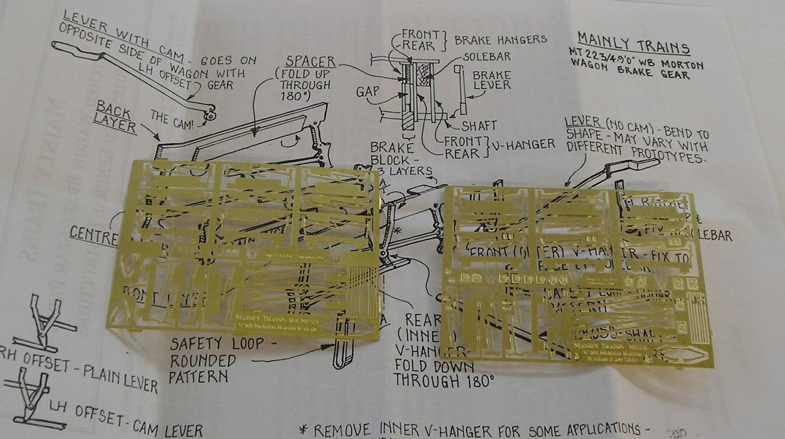
This is what we are talking about:
The kits are here:
A typical kit contents:
Fairly standard. You have etched brass sheets for the coach body and bogies. There are also bags of whitemetal and lost wax brass castings. The roof is vacuformed.
I have the wheels which arrived separately and these are being painted.
16 July 2012
After completing some wagons, I can now get back to these coaches. First the wheels:
I'm not wholly happy with the white band, I'll have to think about doing better.
I started the underframe of the first coach this morning.
Nothing particularly challenging so far. Bolt detail pushes out with an old scriber. I don't have bending bars so getting the solebars folded up without too much distortion took a bit of tweaking. The bolsters fold up with one end being located by a tab - no guessing, very neat. When soldered up, the bolsters really improve the underframe stiffness. Buffer beams fold up into a double thickness and are located by two tabs on the ends - again no guessing.
Next, the step or foot boards. These have tabs that fold up and brackets that also fold up. The tabs go inside the solebar, the brackets outside.
I started by locating the inside tabs and soldering these in place. I turned that assembly over and found that the board is very wavy. Place the underframe on a scrap piece of wood (note that there are protrusions on each buffer beam so the underframe must be supported on something shorter). Hold the underframe flat and use the soldering iron to progressively desolder and reposition the brackets. This may take take more than pass but when you're done, the board should be straight.
Next, take tiny amounts of solder cut from the roll and tack the brackets to the outside of the solebar. Go back and spread out any slight excess of solder. Clean up with a fiber glass pen.
Queenposts are next, these are whitemetal castings. Now, I think everyone is a bit leery of whitemetal because if you linger with the soldering a fraction too long it will devolve into a blob. Soldering whitemetal to brass is done as follows:
1) Use a 25W iron, not the 45W iron that you would use on brass.
2) Use 70C solder and Carrs Red Label flux.
3) Tin the brass with 145C solder.
4) Prepare the whitemetal by filing the oxidised surface clean and smooth.
5) Cut small pieces of 70C solder.
6) Position the casting and liberally flux. Place a small lump of solder adjacent.
7) Apply the iron to the solder and casting just long enough for the solder to melt and bond the casting.
All went well, phew!
Continuing with the assembly.
I shaped some wire for the trussing. This was put into a slot in the queenposts and soldered in place. With some trepidation, I soldered the wire to the queen post and then to the inside of the solebar. There are drawings in 4mm scale in the instructions.
I then folded up the V hangers, making sure the etched holes are the right size by enlarging with a fine broach.
The vacuum cylinders were soldered in place next. You really need to read the instructions carefully to figure out where the brake components go. Thread them onto wire as it goes into the vee hangers and solder in place. There is more rigging to do but I will need to have the bogies done before I can finalise it.
17 July 2012
I added the cast gas cylinders, buffers and coupling hook today. That's the underframe done bar some wire to complete the brake rigging.
You do have the option for gas or electric lighting. For the electric option there are battery boxes and a cast dynamo. I chose gas because the livery will be ca. 1912.
I tackled the bogies next. You can get a compensation kit for this, but these will be rigid. When you cut them from the fret, you get this:
Push out the bolt detail with a scriber. Bearings are soldered into the holes. Make sure you get them the right way round, fold is to the inside. Fold the sides and ends up before the brakes - this way you get less distortion. Reinforce the folds with solder. Fold up the brakes and reinforce these as well. If you are doing 00, you will find the brake shoes are not in line with the wheels - I suppose the kit is optimised for P4.
Add solder to the corners to stiffen everything up. Check for squareness - if not, hold the bogie firmly on its' back on a flat surface and run the soldering iron over the folds.
Trial fit the wheels, check they spin freely with minimal side to side slop. If there is too much slop, hold the bogie by the bearings and squeeze onto the wheels. Touch the iron to each corner so that the sides tighten up.
These run nicely now.
I soldered the bogie compensation springs to the bogie, those castings to the left and right in the picture below.
I had to do a fair bit of fettling of the axlebox castings to get them to sit properly on the bogie sides.
If I had used the waisted bearings supplied, I would have had an easier time. However, waisted bearings are more useful for sprung stock so I opted to substitute shouldered bearings.
I didn't solder the axleboxes because it would have meant soldering on the visible side which would have left a mess. Instead I used super glue - for the first time on this kit.
A word on bogie attachment. You will need to solder a nut to the inside of the bolster. The trick here is not to get solder on the threads. I did it by using a marker on the screw threads and using the screw to temporarily hold the nuts in place:
Here's the underframe married to the bogies:
It is riding low and the bogies have a tendency to foul at the moment - it does run freely. I shall raise the ride and ensure the bogies can swing freely.
18 July 2012
I spent some time today fixing the ride height. It turns out, for me anyway, that two washer (supplied) thicknesses are necessary, one to the bogie and one to the bolster.
By the way, make sure you run a file across the top of the bogie to ensure that there are no etch tags sticking up to catch as the bogie swings.
Another thing to note is that I soldered two pieces of 0.032" wire to one bolster to stop the coach from rocking. The screws on both bogies should be loose. You want one bogie to be free to move just up and down (left in the picture) and the other free to move in all directions. This provides quasi compensation allowing the wheels to negotiate dips and irregularities in the track.
The last thing to note is that I attached the last piece of brake rigging.
Now to turn our attention to the body.
The instructions say to do the tumblehome using a piece of dowel and then make the top and bottom bends. In fact it is better to do the bends first I think. A bending tool would be useful but I don't have one so I resorted to my square nose pliers. First though, I scored the bend line with a couple of passes of my Olfa. This made things easier although I still made a bit of a pigs ear of my first bend. Subsequent bends were better. The inside folds were reinforced with solder.
The tumble home is very subtle and I found it easier to tweak between my fingers. I fashioned a plasticard template to help make the tumblehome more or less consistent.
The ends look like this:
There is a double thickness tab that folds up on itself - this is soldered together. The nuts are also soldered on using the screw and felt marker method.
I spent some frustrating time getting the droplights on. These have to be soldered from the back but there aren't any cues as to whether they are centered or at the right height. I did scribe some lines to help me but these were of limited usefulness. The only thing for it is to get the droplight as close as you can by eye and tack it. Check the other side to see where you are and if you missed, desolder and try again.
I took the completed underframe to the club this evening and ran it through the most challenging pointwork we have - it took these with ease. I am well pleased so far.
19 July 2012
I decided today to look at a representation of interior. I was inspired in this by an article by Andrew Lambert in MRJ 82.
I cut some 0.010" plastic card to be a snug fit, marked with a felt pen and taped the card behind the windows. I marked the windows with a scriber and then cut them out with a sharp Xacto.
Following this I wanted to get the body soldering out of the way.
I soldered the guard duckets on - it was a bit of challenge to get them on square but I managed.
I then soldered the lower door hinges in place. The etched holes should be cleared by inserting the end of an Xacto blade.
Following this I soldered the ends. These are located by fold down tabs on the ends. Reinforce with solder, then clean them up with a file. There are slots in the lower fold of the sides. Again, clear these with a Xacto blade, make sure the tabs fit. Adjust the tumblehome and ensure there are no unsightly gaps between side and end.
Position the end tab in the slots, press down firmly (but don't buckle anything) and solder the lower corner. Make sure the end is flush with the side. If not desolder and correct. To get the end to go in a bit, file of the corner of the tab so that the end can slide a bit. Once happy with this first tack, tack the top of the corner. Again make sure things are flush. If not put the end on a flat surface and apply the iron while pressing down. Once happy, complete the corner with a bead of solder.
Now, join the opposing ends and sides in the same way.
It took me some while to get everything as correct as I could. I finished off with one of the etched compartment separators. I'll come back to these later.
I thought I'd mate the body to the underframe:
Strangely, I had trouble with the screw holes in the underframe not lining up with the nuts on the body. I say strangely because everything has fit perfectly up to now. I've got to think that maybe it's me. Anyway, holes were fettled and the body is on.
21 July 2012
Not a lot of visible progress yesterday, I've come to the point now where there is quite a bit of fiddly work.
I made some grab handles for the doors.
Roof: the kit includes a plastic form that requires cutting down to fit the coach. Once I had done that, I was pleased to see that it hugs the coach very nicely.
At the top of the picture is the raw forming. The completed roof can be seen at the bottom.
I started by cutting the roof to length - actually a couple of mm over length.
Then I cut material from the sides using scissors (the shape is very awkward for a knife). Once I got close, I had a brainwave and got my power sander out. By holding the roof on the vibrating bed (tricky this) I got the roof sanded evenly and accurately.
Finally, I trimmed for the correct length.
Next, the roof was marked out for the ventilators and lamps with a pencil. For this coach everything is on the center line. Having determined the hole positions, I drilled them with a 0.020" drill to begin with. It is easier to locate your hole with a small drill than with a larger one. Large drills can slip before they bite. I followed this with a larger drill, but slightly smaller than the castings. Finally I used a broach to open the holes for an exact fit. The holes were sanded on both sides and slightly countersunk by twirling a large drill bit between my fingers.
There are grab handles at the brake end. These were marked and drilled. A couple of pieces of 0.020" wire were bent to shape.
Before adding the castings, the roof was sprayed white. I put tape on the roof to protect the finish - white gets grubby easily.
End detail: The brake end has slots for steps which are not difficult to install. I drilled holes for the grab handles but had to make them in two parts - it should really have been one piece.
The platform near the top of the end was soldered on with difficulty - I expect I did this wrong but it's on.
The other end has quite a bit of detail.
The instructions are vague on this point. There is a light switch (a gas valve really I guess) about halfway up and an alarm at the top. Dave at Roxey gave me some insight on the location of these. Later on, I found a picture of a Midland coach end that featured these details (The 4mm Coach by Stephen Williams - Wild Swan). My rendition was inspired by this. I assumed a gas line entered the valve from the bottom and it continued into the top of the coach. The alarm is connected to the emergency cord in the coach and opens the vacuum slightly when pulled. This alerts the train crew to a problem. Brackets are represented by thin strips of masking tape. These were flooded with super glue and left to harden.
Today, I gave the components a bath in a baking soda solution to complete neutralising the flux. I also gave them a wash in strong kitchen cleaner.
The underframe received some detailing:
I added footsteps near the guards doors. These were a pain to fit and I probably should have done them earlier. I added a strip of 0.020" thick plastic strip to thicken the footboard, as recommended. This means I need to add yet another washer at the bogie fixing. Vacuum steam heat hoses are supplied as lost wax castings. These were soldered in place.
I have done the couplings - at the near end can be seen a loop of nickel silver wire soldered to a piece of PCB (ornately shaped to cater for the fixing holes and hoses.
At the brake end, I will fit a Kadee coupling to the bogie.
The coaches will run as a fixed rake - hence the coupling loop (the mating coach will have a wire hook). The brake ends will have Kadees to couple to the locomotive and to enable the train to be separated from its loco if required.
I had second thoughts about putting the plastic strip under the stepboards so I removed them and put strip on top. At the same time I did a trial assembly:
28 July 2012
The assembly of the first coach is pretty much done now. I added rainstrips and corbels to the roof.
I also painted the underframe black:
I wanted to paint the coach body but when I started looking at the paint I was given and a preserved coach, the "salmon" colours are very different. I need to talk to my customer about how to proceed.
In the meantime, I have been working on the second coach, a tri-composite (2 compartments each of First, Second and Third, all with lav access - very modern). I'm not going to go into detail on how this is done since the methods are the same. I will say that the experience gained with the first coach made the second much easier going.
I do want to discuss bending. The coach sides have two flanges each which require bending 90 degrees. There is a half etched lined to facilitate this. The recommendation is to use bending bars but, for the first coach I decided to just use flat nose pliers. Mistake! I very nearly ruined the model. The coach sides are quite thin and will cockle very easily. I managed to recover the sides but it was close.
For the second coach I gave a bit more thought to bending. The first thing that occurs to me is that the half etched score line could be deeper to make the bend easier. I scored this three time with my Olfa scrawker. I then came up with this rig:
It's fairly self explanatory, the coach side is clamped between a hard surface and, in this case, a file. Squeezy clamps would be better, but could I find mine?....
Carefully line up the fold line with the edge of the file (dead edge here) and clamp down hard. I simply used my fingers to fold the flange up and a hammer to gently tap the fold up. The first side can be seen. Pliers can be used to complete the 90 degree bend.
The four folds were made successfully using this method:
31 July 2012
Today, I assembled the sides and ends. The result so far:

Rather too much solder on the solebars - ah well.
10 Aug 2012
Coach No. 2 is all but complete:
No. 3 is well on the way.
To update the paint question. I borrowed a friends book on the subject of livery:
"Britain's Railway Liveries, Colours, Crest and Linings", 1825 - 1948 by Ernest F. Carter. Published in 1952 by Burke. I'm kicking myself because I actually found the book on a used book stand and pointed it out to my friend who bought it ($4.50).
In the back of the book is an appendix containing colour samples of 50 colours. The text frequently describes the recipe for the colour. For example, in the entry for LSWR 1900 - 1905, it describes the "salmon pink" as "white lead - 4lb 5oz, burnt sienna - 3oz, venetian red - 2.5oz and middle chrome yellow - 0.75oz".
I was also given additional bottles of paint and thinners, so we're off.
3 Sept 2012
After exhibiting the club layout at Exporail two weeks ago, I took some time off from modelling.
To follow up on my comments above, at Exporail, I was delighted to find a copy of the above book which I snapped up:
As I mentioned, there is an appendix which contains colour swatches of livery colour:
No. 48 is the Salmon colour I will be using. I think that the Bluebell railway coach is painted in a later Salmon Pink from around 1915.
http://www.bluebell-railway.co.uk/bluebell/pics/1520.HTML