Friday, March 23, 2012

Upgrading Dapol's ex LMS Suburban Coaches

by John Kendall

Dapol recently released the subject coaches, composite and brake. These are done from the Airfix tooling. I bought the kits because I really only wanted the bodies. The price is so reasonable that this is worth it and the other bits will make useful spares.

I previously upgraded the underframe and interior, see the earlier Blog entry on that. I had wanted 2 coaches in BR livery and months ago took 2 LMS liveried coaches for that purpose. Unfortunately the paint removal process left the bodies in very poor state so these products were very welcome to me.

This project will cover:

1) Relettering the bodies and
2) Adding SE Finecast flush glazing


I had hoped that the numbers could be left as is but a bit of research (LMS Coaches by Jenkinson and Essery (OPC)) turned up that they are wrong. The problem is that, for example, the brake number M20562, should be M20562M. The reason? Well, after nationalisation, vehicles inherited from the big four had a letter suffix added to the number, in this case M for Midland. These coaches did continue to be built after nationalisation and those that were BR built only had the M prefix. My transfers are not the same size. My perusal of the book found that 20562 was built in 1930 and 16658 (the compo) was built in 1936.

24 March 2012

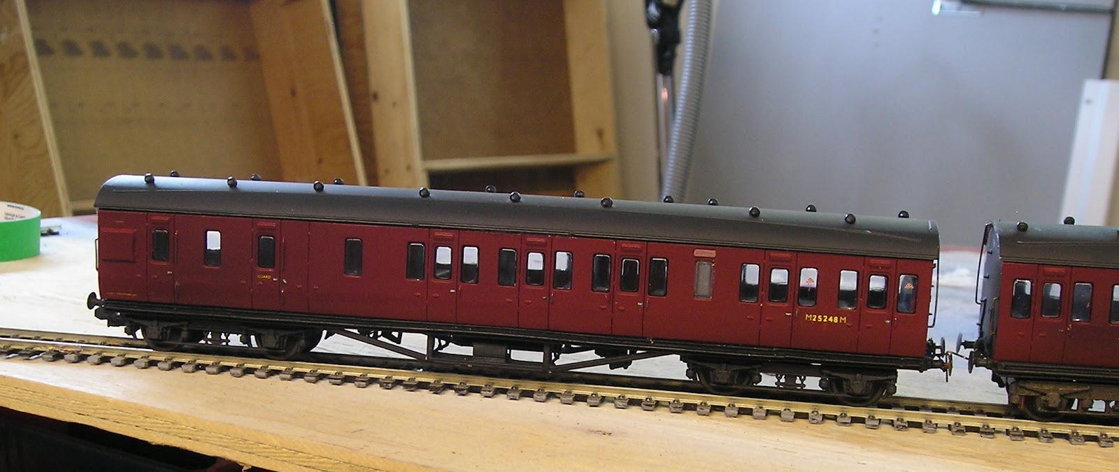
Further study of the above book turned up that the only 57ft Non-corridor stock fitted with Lav. were D1686/1736 (CL) and D1685/1737 (BTL). D1686 and D1685 were period I coaches while D1736/1737 were period II. The most obvious difference between PI and PII was wood panelled ends on PI and steel plated ends on PII. I therefore concluded that the Airfix/Dapol models are D1736 and D1737. For D1736, the number range was 19171 - 19195 and for D1737, the range was 25248 - 25272, quite a small fleet. I repainted the coaches by using an airbrush and Lifecolor BR Crimson. Ends are black. (By the way I already shaved off the molded grab handles and bent some wire into shape.) The coach bodoes were finished with a coat of Glosscote in preparation for transfers.


I have ordered some transfers from Modelmaster so it'll be a week or so before I can get back to this project.

22 April 2012

I finally got to return to these coaches after making some buildings for the layout. I ended up using HMRS numbers but had to use Modelmaster "M"s because the sheet I had didn't have any "M"s left. I also used Modelmaster "GUARD" and "Load..." on the BTL. I found that the varnish film on the Modelmaster transfers tends not to adhere to the model, so after the transfer was dry, I carefully removed the varnish layer. When happy, I sprayed the body with Dullcote.

Once the body was dry, I turned my attention to the Finecast windows. These are vacuformed and quite fragile, being easily crushed by clumsy fingers. A toothpick can be used to tease them back into shape if necessary. Before installation, I added Smoking/No Smoking signs to the inside of some windows.

Note: I should have read the directions more closely because there is a subtle taper to the windows so that they sit flush. I didn't do this and ended up installing about half the windows again to get them oriented correctly.

When installed, the windows are a definite improvement to the Airfix/Dapol but probably not quite as good as Shawplan (but then again, Shawplan don't do windows for these coaches). The coaches were reassembled and the result is shown below:


Notice that the couplings are homemade "hook and bar".  I learned the method from Tony Wright in one of his DVDs and they work great.  There's an earlier post in this blog that describes how to make and install these.

Thursday, March 15, 2012

Downspouts for Buildings

by John Kendall

To go with my earlier piece on gutters, here is how I like to attach downspouts to buildings.


Pretty much all the dimensions are up to the modeller. It's a fairly simple method. Drill the holes in the strip first. I can't seem to get holes centered or in line so it's easier to trim the strip afterwards. The precision of cyano means that the risk to the building's paintwork is minimal. Better still, glue the strips to the wall before it's painted.

If you look at pictures of the engine shed and GWR station, you will see this method used.

John

Monday, March 12, 2012

Upgrading the Airfix 4F

by John Kendall

There has been a fair bit of discussion about the 4F of late. Most recently Hornby released a warmed over version of the Airfix 4F with loco drive. This is disappointing to me since the body appears to be the same as the Airfix body designed in 1975. I am resolved therefore to upgrade mine (a second time) before Bachmann release theirs.

Several years ago I obtained a Kemilway chassis kit for the loco and tender and this worked very well indeed, even in DCC. My thought was to further improve the model using a Loksound 4.0 sound decoder. How hard can that be? I took the following picture partway through the decoder install:


The Kemilway chassis is a clever design being a fold up etched nickel silver affair. It incorprates sprung compensating beams and straightforward pickup design. Chassis is grounded.

You can see that I have installed an 8 pin socket in the tender with wires intended to pass into the loco.

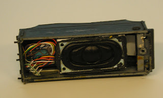
This next picture shows the speaker and decoder in the tender body, quite a snug fit:


So far so good. Now the problems. First the wires wouldn't go easily between the frames and gearbox but I got them in. Next I wired the motor and pickups and did a test run. Well, it did go...for a few seconds, then a short occurred. I tweaked and retested but the short still appeared. Now, in my experience DCC is much more sensitive to shorts than DC so I thought that my chassis construction was probably to blame. In particular I suspected that the brake shoes might be touching the wheels although I couldn't see anything obvious.

To cut a long story short, I finally resolved to re-do the chassis. This also gives me an excuse to try out my Avonside ChassisPro jig. I tore down the Kemilway chassis (It was starting to look quite ratty anyway) and produced two frames with slots for the bearing hornguides, as shown in the following picture:


The picture also shows the 5'3" dia. wheels (Markits) which I chemically blackened. These are suitable for code 75 C&L track (I checked). [Aside, I have an older loco with the same dia. Romford (as it was then) wheels. The flanges are a good 1mm larger on dia. than these.] The hornguides and bearings are also shown. These must be a sliding fit such that the bearing will fall out of the hornguide.

That's where things stand. More to come.

John

Later that day...

I spent some time (no idea how much) assembling the frame sides. I used the ChassisPro to get the bearings located accurately. I must view the DVD again now that I've done a chassis to see where I went wrong. Here are the pictures:


Next, I'll set up the compensating beam.

John

13 March 2012

The first milestone attained - a free running chassis:


Bearings are a sliding fit in the hornguides and axles are a sliding fit in the bearings. It whizzes down the track quite happily.

Here's a view of the compensating beam:


I have tried to make rigid chassis in the past but haven't been able to manage it. Compensation, on the other hand, I find quite manageable.

There's a pair of holes in the frames through which a rod is threaded through a tube. Another rod is soldered to the top of the tube, the ends of which rest on top of the first and second axles. These axles are free to rock and will ride up or down slightly to follow track contours. This helps maintain electric current and improves adhesion.

John

The next milestone - a free running chassis with coupling rods temporarily installed:


It's critical at this stage that the chassis whizzes, as it did before, down the track without hesitation. You will likely find that in the first go, it does just that (hesitate I mean). Assuming the chassis and axles are square (they'd better be!), it is usually a simple matter of reaming the coupling rod holes SLIGHTLY. Do one pair first, then retry. Working on rod holes progressively until all is well. You'll note I retain the rods with wire insulation for this step. The axle nut covers can be seen - I'll swing these into position later.

It's alive! I installed the motor and connected it all to a power supply:


It's running on a Bachrus rolling road.

John

Having assured myself that all was well, I soldered the coupling rod nuts in place (put a piece of paper between the rod and nut to prevent soldering everything solid). After this, I was a bit concerned because the chassis became somewhat tight. After a few minutes thought I remembered an article I read the other day about making Portescap gearboxes quieter ( http://www.cometmodels.co.uk/ , go to the download tab and scroll down). The method involves WD40 and tooth powder. As I don't have any tooth powder and didn't fancy spraying WD40 into a small tin, I used jewllers rouge (we are after all seeking something akin to a Swiss watch) and mineral oil. I scraped some rouge into an aluminum tart tin and added the oil, stirring with a toothpick. I applied this to the coupling rod joints and, just for giggles, the axle bearings. I then pushed the chassis vigorously along my meter test track for a while. I was pleased and not a little amazed to find that it loosened up markedly. I washed the oil/rouge off with lighter fluid and pushed the chassis around some more. The rouge/oil treatment was repeated and after a while I was able to get the chassis to roll down a small gradient under gravity. I felt that was probably as good a benchmark as anything.

John

15 March 2012

Yesterday, I took a break from the chassis while the epoxy securing the PCB for the wipers cured. I decided to have a look at the body to see if I could remove the splashers and make them more to scale. When I tried to remove the splashers from the footplate it basically disintegrated - probably due to age and my clumsiness. I then had a go at making the footplate out of Evergreen strip. To cut a long story short - close but no cigar. Maybe with further effort it could be made to work. I think Evergreen plastic is a bit too soft for this purpose.

So, in the meantime, I have a second Airfix 4F (I was going to use it to make an EM version but I have since acquired a Finecast body kit)....

More to come.

A little more progress to report. I did the wipers using a 1/64" rod and 0.45mm Ni Ag wire. I did try to be neat, honest, but it all seems to go ahoo. Anyway they do work. After that, I fitted the brakes. These are plastic from Alan Gibson:


My rationale on this is that there is no risk of a short from these.

Brakes installed:


The pickups can be seen as well. I put the yellow insulation on them to ensure that they don't contact the chassis. I should add the chassis is live (wheels on the non-pickup side are uninsulated), meaning that at least one side of the loco has good contact and halving the pickup job.

20 March 2012

I spent the last few days working on the body. This is the alternate model of the BR version, which is just as well because that's the version I wnat. The obvious difference is the lack of piston tail rod covers on the buffewr beam.

First, I carefully cut away the splashers. This worked better than I hoped. Once out, the bases were filed so that the height is 5.5mm (1' 5"). This gives a splasher base of 21mm (5'3"). I reckon this is very close to the prototype. When glued back on (happily Airfix plastic is very amenable to styrene cement) the gaps were filled with plastic strip. Chimney and dome are low profile (Brassmasters or Finecast). I fashioned weights for the firebox top and sides and inside the boiler. Still, I'm only at ~ 200 gms.

A fair bit of time was spent thinning the splasher radius and otherwise fettling until the chassis runs freely. I found the RH center splasher to be too short so beefed it up with strip.


It all looks pretty rough but it is coming along.

26 March 2012

I spent the last few days, on and off, working on the body. I have added the handrail and piping along the sides. The left hand piping is brass tube/wire and copper wire, all chemically blackened so that when the paint rubs off it won't show bright.

Here's the body in "works grey":


The thing about grey is that it shows the blemishes and I can see several areas that need further work.

23 June 2012

This project has been languishing due to other priorities.  You can get an idea of that from more recent posts.

Today, I thought, enough already time to get on with it.  I had painted the chassis black and spent some time installing wheels, oiling and loosening things up.  I decided to do trial fit and see how things ran.  Well, they don't.  There is too much interference between wheels and splasher.  Looks like Airfix had the right idea in the first place.

A few months ago I bought an old Finecast 4F second hand.  When I do this, I never have high hopes, and in this I wasn't disappointed.  It was clear that the castings were from the very early version of the model.  Worse, the chassis is whitemetal and the motor is an X04.  The good news is that the wheels are Romford, although I expect that these will be pre RP25 (this is TBD).  I should be able to turn down the flanges using my Dremel and a file.

The model in it's built form was unacceptable so had to be disassembled.  How to do it?  Well, I didn't even know how it was put together.  Low melt solder is advocated by most modellers, but many people use glue.

I dumped the body and tender into a pot of boiling water.  Low melt solder has a melting point of 70 deg C, so this will melt any solder.  After about a minute, nothing seemed to be happening so I removed the components from the water and dropped them into a bowl of cold water.

It took several minutes but I noticed that the joints were weaker and the more I teased the parts, the looser they became.  Eventually I ended up with this:


I will need to see which parts are usable and whether I need to rob parts from the Airfix body etc.

John

Sunday, March 11, 2012

Coal Stage

Last Saturday I decided to make a coal stage to go with the Engine Shed recently completed. The model was inspired by an example built by Stephen Williams for his "Faringdon" layout. The layout is discussed at length in a 3 volume Wild Swan set "Great Western Branchline Modlelling".

I used plastic sheet and strip. To simulate wood I scraped some coarse sandpaper over the plastic. An Olfa carpet cutter ("scrawker") works well to scribe planks.


Painting was a black/brown mix. Once dry I airbrushed first earth, then black. To finish I added a pile of coal and some tools.

It's very satisfying to do things like this. Sure there are kits, but this is unique and, best of all, cost next to nothing since I found most of the material in my scrap box.

John

Friday, March 2, 2012

C&L Laser Cut Wood Kit of a GWR Station

Following on from the last post, I have completed the subject kit. Details can be found here: http://www.finescale.org.uk/index.php?option=com_virtuemart&Itemid=55.

You can also read a review in the July 2011 edition of British Railway Modelling, so I won't spend time going over general construction. The recommended glue is Aliphatic Resin (in it's basic form this is Lepages Yellow Carpenter's Glue). It comes in smallish bottles, similar to those used for cyano, but it seems to be unheard of here. I used cyano, contact cement, PVA and Yellow glue as the need presented itself.


Opening the box:

Wow! Loads of beautifully cut birchwood ply pieces. Windows and doors come in for particular praise. However, upon examination of the main walls I was dismayed to find that they are butt jointed and thus lose the brick detail at the ends. The same issue is evident with the chimneys. I had to sit and think for a few minutes. My decision was to reproduce the walls out of plastic card using the wooden pieces as templates. My philosophy is to make a decent model using the kit as an aid.

Making a start:

First order of business was to measure up and cut the walls to shape. Note: Door and window openings have to be cut 0.5mm wider on each side (I do this by eye). Offer up the windows and doors to make sure you are close to the right dimension. After that I glued on SE Finecast English Bond brick (Slaters works equally well). I then glued strips of brick down the edges of the doors and windows to try and give these an appearance of brick (hence the need to cut the apertures oversize).


Wall ends were bevelled 45 degrees(ish). When the strips mentioned above are dry, trim flush to the inner wall. Simply cut the window and door openings out now. Again offer up the doors and windows, slight sanding should get everything to fit. I added the lintels and sills at this point using cyano.

I spent quite a bit of time making a representation of the interior using floors and other details from Scalescenes Interior Elements kit: http://www.scalescenes.com/scratchbuilders-yard This is entirely optional.


Interior walls provided in the kit should be glued back to back.

The walls are glued together, made square and left to dry. Do ensure the walls are square otherwise the roof won't fit properly.

Painting:

Obviously painting is a crucial part of any kit. When I make a model, always in the back of my mind is...painting. The order of construction in many kits ignores the need to paint. I like to make subassemblies and paint these, avoiding hard to reach areas. You can go back later to touch up.

Walls: Before assembling together I start with a coat of red oxide car primer. Allow to dry then apply a thin wash of mortar colour (I used acrylic Concrete). After about an hour or so, get some ammonia based window cleaner and cotton swabs (applicable to acrylic paint). Dip the swabs in the cleaner and gently rub the walls to remove surface Concrete colour. The mortar course should remain concrete colour. Do this until you're happy. Don't rub too hard. Dry the walls and get your brick red colour. I simply added red to Tamiya Flat Brown. Dry brush the brick colour trying not to get it in the mortar courses. After this is dry, I lightly brushed some rust coloured powder on the walls. Finally, seal everything with matte varnish.

Windows: These are (in my mind) cream. I don't get all OCD about accurate colour and used PollyS D&RGW Cream. However, before applying the top colour, spray paint the windows (and doors) with flat white. This covers much better than brushed on white. When dry, the cream goes on very nicely.

Doors: These need to have the panels painted cream while the doors are chocolate brown (here I use Tamiya Flat Brown). Painted panels are a problem for me since no matter how hard I try, I can't seem to get a satisfactory result. In this case, however, I hit on a neat solution. The doors are thin enough that I was able to cut the panels out and paint the door. I then got a piece of pastic card and painted it cream, gluing it to the back of the door. Finally, I drilled a 0.020" hole, and bent some fine wire to make door handles.

Glazing: The supplied glazing will go straight on the backs of the doors and windows. It is covered with protective film. I cut mine to shape because of the interior. Best to follow the instructions here - I didn't.


Roof Trusses: These are explained in the BRM article. These fit very nicely. Lots of spare bits are supplied, some of which serve no obvious purpose (always worrying). I elected to stain the projecting rafters.

Canopy: Do a trial fit of this. If your main building isn't true, you will find out now. I used cyano to fix the ribs. The spacer tool is just a bit too wide since by the time I got to the end, my rib spacing was off quite a bit. I should have done some measuring. I sprayed the roof with grey car primer and then, when dry, painted it with PollyS Grimy Black.

Barge boards: These come on a "fret" with the layers. Again this is explained in the BRM article. Essentially start with the wider strips and glue these to the top of the bargeboard. Then, take the narrower strips and do the same.

Canopy assembly: Straightforward - glue the flat roof to the projecting rafters.

Main Roof: Four pieces of pre-cut plywood are supplied. These are cut slightly large so careful study and trimming is needed to get them to fit snugly. Finally sand the joints smooth.

Roof Tiles. Pre-cut paper tiles are provided. I used PVA in a jar with a small brush. Apply the PVA to the plywood and while the glue is wet, lay on a strip of the tiles. Let this dry for a few minutes. Proceed to the next strip orienting in accordance with the instructions. Don't rush. Finally apply the ridge tiles. Tip: make a small cut at each end of the ridge tile strip. Turn it over and, using the BACK of an exacto blade, score a line. This will make it easy to bend.

Main Roof Painting: I masked off the entire building. I used red oxide car primer on the roof. When dry, my brick colour was used.

Bargeboard Assembly: I had to think about this because the location of these is not obvious. A look at the photos on the site helped me to figure it out. Snip off about 4mm of each rafter, sand. The bargeboards are glued to the canopy flush with the edge of the canopy. Fitting needs to be done carefully. The corners need to be filed to a 45 deg. angle to make a crisp joint.

Chimneys: I assembled the wooden chimneys that were supplied but I was unhappy with them. I elected to make them using plastic card and brick. The cast chimney pots should be sanded to get rid of flash and mould lines.


Notice Boards: Some lovely boards are supplied but I couldn't see how I could paint them convincingly. I made my own from plastic card & strip. Text was done with Powerpoint.

Conclusion: The kit makes up into a stunning building as Nigel Burkin said in his article. I'm not convinced that it's a good idea to cut and etch brick walls from wood. The mortar course depth isn't deep enough and, as I mentioned, the end wall detail is lost. Far better to use plastic for this.

Edit 10 March 2012

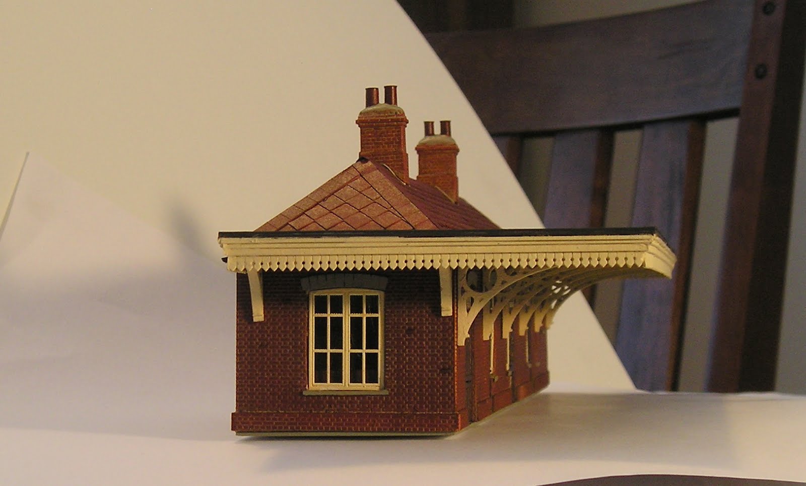
I have now weathered the building and photos follow:


John Kendall

Friday, February 24, 2012

Mikes Models GWR Yard and Water Cranes

For our branchline, I recently bought some of the subject kits. These can be obtained from Holt Models (http://www.holtmodelrailways.com/search.php?search=mikes). I thought I'd try to provide some insight in the construction of these since I think most of us are used to building plastic kits.

General:
The kits are primarily in cast white metal. The first thing to do when dealing with white metal is to wash the parts with soap and water. I happened to use Windex (window cleaner). Once dry examine the parts and remove flash by sanding or scraping the edge of a modelling knife along the seam. Look at all the holes where parts will have to pass through. Dry fit and use a reamer to to open the diameters until you get a snug fit. Its a good idea to give the mating surfaces a rub with a fiberglass pen

There is some brass chain in the kits. I used Carrs chemical blackening fluid to darken these. Painting tends to clog the links.

Yard Crane (MM37):

Try to work out where everything goes before assembly. For this kit, it is certainly not obvious. Even the photo in the link seems to me to be incorrect. Once I got everything sorted assembly was fairly straightforward. I used medium viscosity cyano adhesive. The only issue I had was getting the crane to swivel. It took a few minutes of sanding the spindle before the crane swung freely.


Note the position of the small gear wheel and brake. It took me a bit of thought to decide to put these where you see them. I couldn't find a picture of this specific crane. My logic said that the operator would want to have the crank and brake close together so, in my configuration the crank can be turned by the right hand and brake operated with the left - this seems right.

I made a plastic card base painted with aged concrete.

Painting:
I always like to prime my models and when dealing with metals, I believe this to be most important. I use car primer, grey for the crane. When dry, having no idea of the prototype colour, I used grimy black for the frame and gunmetal for the gearwheels. Once that was dry I weathered the model. Everyone has their own method but mine is fairly simple - I simply airbrushed a light coat of earth followed by a light coat of black. I then drybrushed some rusty powder here and there.


Water Crane, Platform (MM6) & Floor Mounted (MM161):
These are very straightforward and assembly is pretty obvious. On examination, my first thought was that the guy wire supports (cast in white metal) are too fragile (in fact, if memory serves, at least one had already broken off). I decided to replace the guy wire supports with 0.032" brass wire. I snipped off the supports, sanded smooth and drilled. It's a good idea for things like this to start with a small hole and work up. You have a better chance of centering the hole. I began with a 0.020" drill (dip the drill in oil, this will improve the cutting and prevent jamming) and when deep enough switched to a 0.032" bit. Wire was glued in and cut to length. I also drilled 0.020" for the guy wire at the other end of the crane. Finally I replaced the cast hook on the drain with a wire version. I also decided to replace the chain attachment with 0.020" wire. Again medium viscosity cyano is the adhesive.


I constructed a two piece base in plastic card and strip. I wanted to be able to plant the cranes in a layout mounted base for exhibition.

Painting:
Again, primed with grey. After that, since the top coat is very light, I sprayed again with Testors Flat White. THis time I was able to find a couple of pictures of GWR water cranes. I used D&RGW Cream for the body colour (I never seem to have the actual railway colours) and Humbrol Matt Sand. I picked out details in black. Weathered with earth and black and brushed with a light dusting of black and rust powder here and there.

Conclusion:
I am very pleased with how these turned out. A modicum of care (as with all kits) will result in an excellent result. Remember that we should be building a model of something using the kit as an aid. Building a kit is something else again. I am never shy to discard parts I don't like or change something.

Saturday, February 11, 2012

Engine Shed for the Branchline

We are constructing a branchline for Allingham based on GWR/Western Region. The line ends up at a terminus station serving a small town. We decided to construct this section of the layout to fine scale (code 75 rail, hand built points) vs the code 100 railof the main layout.

I put my hand up to build the engine shed and we decided upon a small affair based on that at Tetbury. Fortunately we had a book to hand that provided photographs and line drawings of the shed to 4mm scale.

The finsihed product is shown here:


Construction is 0.040" Evergreen plastic sheet overlaid with Slaters English Bond brick. Various plastic strip was used for detailing.