by John Kendall
I was asked, the other night, to install Kadee couplings a club member's rake of Hornby Pullman cars. These are brilliantly done and favourably reviewed in several places. There are, however, two versions of coupling. Most recently the cars are fitted with NEM pockets and these, of course, are a doddle to do. The cars are also fitted with the coupling extension cam for going round curves. I am no fan of these and, in my opinion, the mechanism is really only necessary for really tight curves. Four of the cars in the rake have the earlier coupling, making the job into a major task.
The photo above illustrates the problem. I stared at it for some while. Thought about, and started working on, a mod. to the coupling mount to take a Kadee. However, I decided in the end that it wouldn't do. Reluctantly, I decided to do away with the coupling extension cam and to mount a #20 Kadee directly on the bogie.
Bogies do pull out with a firm tug. The first thing to be noticed is the wire for the interior lighting. This should be pulled out and cut at the heat shrink covered splice. (In one case the wire inside was tangled and pulling on the wire broke it. I had to remove the body (easy enough to do) to access the wire inside and bring it out through the bogie pivot hole.
I checked the back to back measurement with a DCC Concepts gauge and, to my surprise, this seemed correct.
Next undo two screws attaching the keeper plate for the coupling extension. Remove and discard the coupling extension. Re attach the keeper plate (it doesn't do anything now).
To the bogie next. Remove the front axle. (Note that there is one un-insulated wheel on each axle, so when removing these pay attention to this when re-installing).
I built up the front of the bogie with plastic strip in order to take a screw and position the Kadee at the correct height and distance.
1) Cut a piece of 0.040" strip to length to fit over the front of the bogie. The plastic used for the bogie is impervious to plastic solvent so I use a pin and superglue method.
2) Drill two holes in the strip for 0.032" wire.
3) Drill two holes in the front of the bogie at the same locations (it's a good idea to use the strip just drilled as a jig).
4) Take a 0.100" x 0.125" piece of strip cut to the same length as 1) above. I beveled mine to make them look a bit neater.
5) Insert two shortish pieces of brass wire into the holes in the bogie, securing with superglue.
6) Cut a piece of strip about 10mm long.
7) Now, push the strip in 4) over the brass wire and secure with plastic solvent.
8) Glue the strip in 6) to the center of the assembly.
You should have something that looks like this:
The photo shows the bottom and top of the bogie.
Next, drill a hole directly adjacent to the center piece of strip. The size of hole will depend on the kind of fixing you use. Any screw with sufficient will do. The Kadee Delrin screw is convenient and you can tap for this using the Kadee tool.
Drill your #20 Kadee just ahead of where the split tails end. Cut these off.
Secure the Kadee. I like to add some superglue to the fixing to prevent loosening.
The Kadee fitted bogie looks like this:
The only question mark will be distance from bogie center. I chose this such the the knuckle hinge is about even with the buffer head.
Remove the V shaped plate inside of the buffer beam to ensure that bogie swing is not restricted.
You will have to splice the wires together and stuff them into the body.
When all is done the coaches look like this:
I'm also fitting working gangways.
18 June 2012
A quick update on progress. I've had a couple of test sessions. There is one spot on the circuit where a couple of cars have derailed, at different times. It looked to me as though there was something snagging the bogie as it exited a curve. On examination there seemed to be a potential foul between the rear of the bogie and the trussing. I scraped down the back of the trusses so that there is a bevel there now. Yesterday's session revealed just one car with a tendency to derail at the same spot. I have used my Dremel to grind down the top front of the built up plastic card on the bogie to give a bevel and more clearance. I also rounded over the rear of the bogies slightly. Finally, I also snipped off the top of the clip that holds the glazing. I'll do another test on Wednesday.
Tuesday, June 12, 2012
Tuesday, June 5, 2012
Weathered Class 23 "Baby Deltic"
by John Kendall
David Finch roped me into weathering his new Class 23 loco from Heljan. I'm no expert on this machine but it looks good to me and runs extremely well.
More information can be found here: http://en.wikipedia.org/wiki/British_Rail_Class_23
David Finch roped me into weathering his new Class 23 loco from Heljan. I'm no expert on this machine but it looks good to me and runs extremely well.
More information can be found here: http://en.wikipedia.org/wiki/British_Rail_Class_23
Saturday, May 19, 2012
Royal Mail Train
by John Kendall
19 May 2012
A couple of weeks ago I was at a show with the usual trade stands. On my travels I came across Bachmann's latest Royal Mail TPO. Now I had seen this when it first came out several months ago and was tempted then. It would certainly be nice to have a mail train. However, my researches and questions turned up that main line mail trains tended to be quite long and included several TPO (sorting) and TSO (stowage) coaches. The best source I have found is the Wikipedia entry on the Great Train Robbery: http://en.wikipedia.org/wiki/Great_Train_Robbery_(1963).
The entry says that the loco was a class 40 and that the train was 12 coaches long. Interestingly, it says that the second coach was a High Value Package vehicle containing money and registered mail. Unfortunately we are not told what type of vehicle this is. There was Mk 1 Bullion van developed but this entered service around 1968. My suspicion is that the Bullion van came about as a result of lessons learned from the robbery.
So, I can't do a main line mail train. Oher sources indicate that mail trains included GUV and BGs. The last coach in the train was a brake second (BSK).
My compromise therefore is to do a feeder mail train if you will and mine will be made up as follows:
GUV (Bachmann)
TPO (Bachmann)
Only the one coach but I had to show both sides - beautifully done!
BG (Bachmann Mk 1)
BSK (Hornby ex LMS Period III)
Workscope:
1) Install working gangways.
2) Install hook and loop couplings along with vacuum/steam pipe
3) Weather the TPO.
4) The maroon BG is an ex LMS vehicle and is quite an old model. This will need considerable work. The underframe will have to brought up to standard and the windows flush glazed.
Ex LMS BG
I decided to begin with this coach since it requires the most work. Now, the purist would say that the underframe should be redone completely, similar to what I did with the Mk 1 Suburbans. I thought I'd try a bit of a shortcut approach here.
Here's the underframe and the bits I plan to use:
Comet Models to the rescue again for vacuum cylinders and V hangers. Voltage regulators as well. I have a set of Finecast flush glazing. The dynamo is from a batch of old PC coaches that I stripped down for parts.
As for where everything goes...Comet is a useful resource here as well since their site has downloads of photos of completed models and instruction sheets.
First I removed the underframe and trimmed the unwanted mouldings. I got rid of the old vacuum cylinders and voltage regulators. I marked out where everything should go. The original U/F didn't even have a dynamo.
Next, I added struts to the transverse trusses using 0.040x0.040" plastic strip.
This does look way too heavy and should really be in brass strip.
I folded up the V hangers and threaded a wire onto which I put the brake actuator and crank. (The crank is from a Mainly Trains goods wagon brake gear fret).
You will see I put a scallop in the base of V hanger - this is so the cylinder will sit in the right place. A soldering tip: cut the wire too long and solder from the outside. That way excess solder will be on the waste.
22 May 2012
LMS 54' underframe is done:
I discovered when fitting the brake cylinder assembly that the original floor was too low so I removed and replaced with a new one using 0.040" plastic card. A very useful resource for information on these is Historic Carriage Drawings by Jenkinson. The book has detailed underframe drawings. One thing that surprised me is that there is no dynamo shown on the 54' U/F drawing and indeed, I couldn't find a place where it would fit. Also to be noted is that, as this is a brake vehicle, there is a link from the center of the coach to the brake cylinders. This would permit the guard to control the train brakes.
I was reminded that Mk 1 and LMS coaches had steps at opposing ends of the coach. These are modelled on the new Hornby Stanier coaches but not on Bachmann. I made some steps from 2mm wide brass waste and strip:
I also spent some time yesterday making flexible corridors:
Their construction is discussed elsewhere. LMS ones are in the middle. I did have the foresight to go to the art shop to get a couple of quite large sheets of black paper.
23 May 2012
I was busy today finishing up the couplings etc.
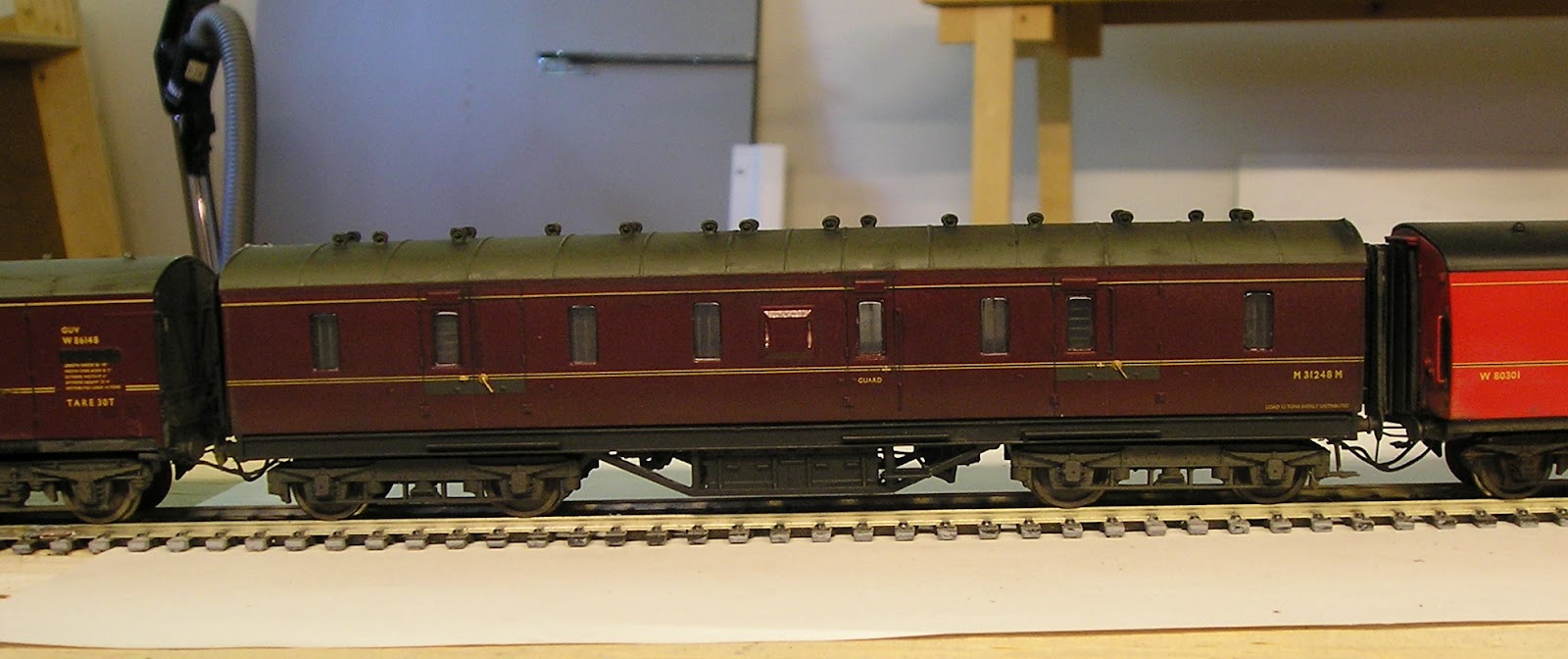
From left to right; GUV, ex LMS BG, TPO, Mk 1 BG and ex LMS BSK. Note all coaches have a representation of dynamo belt. I used 1mm phosphor bronze strip for this. Using the bogie as a guide I drilled a hole in the U/F so that the belt anchor wouldn't foul. Wrap the strip around the drive wheel and bend it down (towards the U/F) to form the anchor. Super glue the belt to the anchor point and pulley.
Also to be noted are steps near the buffer beams of all but the GUV.
24 May 2012
I had to do some fettling of bogies and PCB to get bogies to swivel freely and bogies were installed today. Here are some pictures:
19 May 2012
A couple of weeks ago I was at a show with the usual trade stands. On my travels I came across Bachmann's latest Royal Mail TPO. Now I had seen this when it first came out several months ago and was tempted then. It would certainly be nice to have a mail train. However, my researches and questions turned up that main line mail trains tended to be quite long and included several TPO (sorting) and TSO (stowage) coaches. The best source I have found is the Wikipedia entry on the Great Train Robbery: http://en.wikipedia.org/wiki/Great_Train_Robbery_(1963).
The entry says that the loco was a class 40 and that the train was 12 coaches long. Interestingly, it says that the second coach was a High Value Package vehicle containing money and registered mail. Unfortunately we are not told what type of vehicle this is. There was Mk 1 Bullion van developed but this entered service around 1968. My suspicion is that the Bullion van came about as a result of lessons learned from the robbery.
So, I can't do a main line mail train. Oher sources indicate that mail trains included GUV and BGs. The last coach in the train was a brake second (BSK).
My compromise therefore is to do a feeder mail train if you will and mine will be made up as follows:
GUV (Bachmann)
BG (Bachmann ex LMS)
TPO (Bachmann)
Only the one coach but I had to show both sides - beautifully done!
BG (Bachmann Mk 1)
BSK (Hornby ex LMS Period III)
Workscope:
1) Install working gangways.
2) Install hook and loop couplings along with vacuum/steam pipe
3) Weather the TPO.
4) The maroon BG is an ex LMS vehicle and is quite an old model. This will need considerable work. The underframe will have to brought up to standard and the windows flush glazed.
Ex LMS BG
I decided to begin with this coach since it requires the most work. Now, the purist would say that the underframe should be redone completely, similar to what I did with the Mk 1 Suburbans. I thought I'd try a bit of a shortcut approach here.
Here's the underframe and the bits I plan to use:
Comet Models to the rescue again for vacuum cylinders and V hangers. Voltage regulators as well. I have a set of Finecast flush glazing. The dynamo is from a batch of old PC coaches that I stripped down for parts.
As for where everything goes...Comet is a useful resource here as well since their site has downloads of photos of completed models and instruction sheets.
First I removed the underframe and trimmed the unwanted mouldings. I got rid of the old vacuum cylinders and voltage regulators. I marked out where everything should go. The original U/F didn't even have a dynamo.
Next, I added struts to the transverse trusses using 0.040x0.040" plastic strip.
This does look way too heavy and should really be in brass strip.
I folded up the V hangers and threaded a wire onto which I put the brake actuator and crank. (The crank is from a Mainly Trains goods wagon brake gear fret).
You will see I put a scallop in the base of V hanger - this is so the cylinder will sit in the right place. A soldering tip: cut the wire too long and solder from the outside. That way excess solder will be on the waste.
22 May 2012
LMS 54' underframe is done:
I discovered when fitting the brake cylinder assembly that the original floor was too low so I removed and replaced with a new one using 0.040" plastic card. A very useful resource for information on these is Historic Carriage Drawings by Jenkinson. The book has detailed underframe drawings. One thing that surprised me is that there is no dynamo shown on the 54' U/F drawing and indeed, I couldn't find a place where it would fit. Also to be noted is that, as this is a brake vehicle, there is a link from the center of the coach to the brake cylinders. This would permit the guard to control the train brakes.
I was reminded that Mk 1 and LMS coaches had steps at opposing ends of the coach. These are modelled on the new Hornby Stanier coaches but not on Bachmann. I made some steps from 2mm wide brass waste and strip:
I also spent some time yesterday making flexible corridors:
Their construction is discussed elsewhere. LMS ones are in the middle. I did have the foresight to go to the art shop to get a couple of quite large sheets of black paper.
23 May 2012
I was busy today finishing up the couplings etc.
From left to right; GUV, ex LMS BG, TPO, Mk 1 BG and ex LMS BSK. Note all coaches have a representation of dynamo belt. I used 1mm phosphor bronze strip for this. Using the bogie as a guide I drilled a hole in the U/F so that the belt anchor wouldn't foul. Wrap the strip around the drive wheel and bend it down (towards the U/F) to form the anchor. Super glue the belt to the anchor point and pulley.
Also to be noted are steps near the buffer beams of all but the GUV.
24 May 2012
I had to do some fettling of bogies and PCB to get bogies to swivel freely and bogies were installed today. Here are some pictures:
I'm quite pleased with how these look. The vac/steam pipes look pretty effective. The biggest issue I found (this is the first time the rake has been coupled) is that the gangways between the TPO and second BG are tight. I suspect the hook needs to be repositioned.
I hope to give the rake a test on Sunday.
Tuesday, April 24, 2012
Upgrading Bachmann BR Mk 1 Suburban Coaches
by John Kendall
24 April 2012
These coaches are generally very good. Body mouldings are crisp and decoration is top notch. I have two lots of these: 4 in crimson and 4 in lined maroon. The latter batch came out last year and have improved decoration in the form of window transfers and overhead warning flashes. By the way, by using a magnifying glass, I determined that the blue sign on the window of the brake coach compartment adjacent to the lav. says "LADIES ONLY".
However, being a couple of generations old, the coaches are sorely lacking in two significant areas:
1) Glazing - definitely NOT flush and
2) Undeframes - very clunky and crude
This project will be in two parts broken down into the categories above.
I will first of all add flush glazing from 2 sources. The first will be the Extreme Etching laser cut flush glazing from Shawplan. I have never seen a review of these so I think one is overdue. The second source will be SE Finecast flush glazing. I used this for my ex LMS suburbans - see post below.
The next phase will be to rework the underframes. For this I will use components from Comet Models.
I have eight coaches to do (groan!). The Shawplan glazing pack can be seen on the left. Next to it is a pack of underframe components including vacuum cylinders, battery boxes, dynamos and assorted other bits. The next pack contains switch boxes and oil valves. Finally there is a pack of buffers and jumper cables.
I've been working on the flush glazing and here is the result:
The brake on the left has flush glazing (in case you didn't know).
The underframe is held on with quite sturdy clips. The best way to get it out is to lever the coach side away from the underframe using an Xacto blade and pry the other side with another Xacto. The lower step is quite fragile so be careful (ask me how I know).
First, to use the Shawplan glazing you must REALLY want to flush glaze your coaches. It is very fiddly. I got off to a bit of a rough start but with practice I got in my stride. There are NO instructions and the best I could do was find some photos on the Shawplan site/blog.
First question: what to use for adhesive? I opted for Future (old). I understand that there is a new formulation which is not as good for this job (I imagine it does polish floors though).
The pack contains door windows and compartment windows. Remove only those windows you want to install from the fret. I used a sanding stick (nail file) to smooth the corners. I decided to begin with the door windows. The windows go in from the front and you need to understand that there is a very subtle taper which means you need to be careful that the window goes in the right way up. For the door windows there is also, again, a very subtle difference in corner radius delineating top and bottom. Get it wrong and there will be a gap at the bottom.
I used a small flat brush to apply the Future very carefully to minimise getting the stuff on the coach side. When not in use, put the brush in a container of water. Do about half a dozen at a time and allow to dry for about 15 minutes. Check that the windows are still where you want them. Any that are out of line will be obvious when viewing along the length of the coach.
I have done a second open and found that the compartment windows don't seem to fit as well as on the brake. I put this down to tiny differences in window opening dimensions. Running a curved Xacto blade along the inside of the windows will help to open them up. Yo may want to fettle the windows a bit as well, particularly the corners.
25 April 2012
Since I had the coaches apart and the windows are much clearer than the old ones, I decided to improve the interiors somewhat. Nothing fancy but just painting floors and seats. I'm not entirely sure and I did do a search but I think 2nd/3rd class seats were red. The simple representation of compartment pictures is taken from a Bill Bedford seat download, free on his site: http://www.mousa.biz/downloads/coach_seats.html
The coaches look brilliant to me as evidenced by this picture:
I added security bars on the parcels compartment window of the 2 brakes by:
1) chemically blackening 0.020" and
2) gluing it into place
I still need to add "No Smoking" decals.
That's phase 1 a) done. Phase 1 b) will add Finecast flush glazing to 4 other coaches.
2 May 2012
I completed Phase 1 b) today.
The effect is good although perhaps not as crisp as the Shawplan. Finecast glazing is vacuum formed, a technology quite a few years old. I am pleased though.
The windows come as two sheets, one for door windows and one for compartment windows. I cut them out with scissors. These go in from the back and most of the time they just pop in, held firmly enough to do the whole coach.
In many cases, the windows wouldn't go in and for these I resorted to a curved Xacto blade to scrape the window openings and to carve the corner radii. Do a little at a time and keep trying your window until it goes in. The sheet does include windows of varying sizes. Some of the door windows wouldn't stay put so I had to glue (Future floor polish, aka Kleer) these one at a time. One advantage is that the Future can be applied to the backs of the windows reducing the risk of getting it all over the coach sides. I used a Qtip to mop up excess Future from the windows.
At the top is the Bachmann underframe and below that are the Comet components. The Jumper Cables and Buffers are really part of the body. I will have to think about whether I use the buffers, the Bachmann ones are not bad.
7 May 2012
I got two proof of concept underframes done over the last week. One is the Comet U/F pretty much out of the packet. The other is a hybrid using Comet components but the Bachmann plastic U/F with a great hole in the middle.
Here are the results:
First as a baseline, here's a side view of the original U/F:
Next a side view of the Comet U/F:
And finally, the hybrid:
Here's a view of the three undeframes from underneath:
Some comments on the process.
1) Comet underframe.
The floor is etched with the center struts as a fold up, but leave this until later.
The sides fold up and are reinforced by solder. These are designed for brass sided coaches so I found that the sides wouldn't go into the coach body when vertical. I folded that at an angle to provide a lead in. I also removed the floor retention tabs and thinned the coach sides by scraping with a knife. The U/F can be made to fit.
Solebars are tabbed so installation is not an issue, however, before fixing, the stepboard must be considered. There is no location device in the kit for this. The instructions call for drilling 0.7mm holes to accept wire that will support the steps. I marked a line 1mm up from the bottom of the solebar, while it was still on the fret and drilled at each tab.
Install the solebars next. Now, here's what I should have done: drilled for 0.020" and run 0.020" wire through both holes widthwise in the solebars and solder. Next take the step (the 2mm wide strip on the fret) and, starting from the center of the coach, solder it to the support wires. With these running across the width of the coach they won't go all floppy when the solder melts. Do this for both sides. Then reinforce with more solder along the length. I found the 0.032" wires to be too thick and obtrusive. When happy that the step is straight, cut the wires inside the solebar and grind/file flush. I also ground the support wires from under the step - the extra reinforcing solder will hold the step in place.
The center struts can now be folded into position now and soldered.
You will find there is a big hole in the floor of the U/F. First, I took the weight from the original underframe and glued that to the inside floor. When dry, I cut out 0.020" plastic card to shape and glued that to the outside floor to fill the cavity.
Solder the V hangars and voltage regulator support frame.
There are two lots of whitemetal lateral struts. These will need filing and fitting. I used cyano.
To fit the oil valves, drill a 0.020" hole in the inner strut (the location of these and other components can be seen on the instruction sheet that you download from Comet's site). Drill a hole in the valve support and glue wire to it. Fix to the inner strut with cyano. (I always like to pin small components).
I added a representation of brake rodding and dynamo belt.
I used the pinion from the plastic underframe, cut to the appropriate length to support the bogie.
2) Hybrid underframe.
Remove all the detail from the underframe. I used a Dremel with cutting wheel for this. Then, with the Dremel, cut through the floor and remove everything up to the end of the struts. Make the hole done by the first cuts too small, it's very easy to remove too much. Once you have the hole, remove material up to the bevel. Leave enough material for strength.
You will need to cut the Comet floor to the same length and width and the hole you just made. It will take some fettling to get both parts to fit nicely. The Comet floor needs to be about flush the bottom of the plastic floor.
Carry on as before soldering and fitting components.
Make two pieces of plastic card to overlap the hole by the distance from the edge of the Comet floor to the weight. Glue to the inside floor (I used Contact Cement). Next, make a filler piece of 0.040" card to the width of the overlap and glue with styrene cement.
Glue your Comet sub assembly to the bottom of the coach. Finish up the details.
A bit of trivia: the plastic U/F weighs 80 gms, the hybrid 100 gms and the Comet 120 gms. I don't think it matters all that much since most suburban trains we run will have 2 or 3 coaches - occasionally 4.
Conclusion:
I think both models look the part. Once painted I think one will be hard pressed to tell the difference. Both are a lot of work, for different reasons. I'm inclined to go with the hybrid because it's a drop in replacement.
8 May 2012
Having decided to use the hybrid method I spent an hour or so this morning, removing the detail from 2 underframes, shown here:
Width of hole is 30mm, length from end of U/F to hole is 54mm. Length of hole is 117mm.
The next step is to build the Comet module and pack the U/F to receive it.
At the top is the packed U/F (white plastic) upon which the Comet module will sit. At the bottom is the floor side of the U/F showing packing pieces glued on. The plastic U/F is about 0.060" thick. At the bottom is the Comet module with the weight glued to it. The modules are cut to length but not yet cut to width. There is not a lot left of the module once the struts have been folded up - the weight provides stiffness to the module. 0.020" card was glued into the cavity to give a flush floor.
9 May 2012
I spent some time today cutting, filing, grinding and otherwise fettling the Comet modules to acheive a snug fit in the underframe. These have been glued into place:
12 May 2012
I started adding details today:
The V hangers were soldered in and all but the center struts glued in place with cyano. Battery boxes were fixed with contact cement.
14 May 2012
I completed the underframes this morning. I did discover that the Bachmann underframe is incorrect for brakes and the battery boxes should be directly opposite one another:
I painted the four underframes with grey primer:
Brakes are at the top. Now with a coat of flat black:
17 May 2012
I've been putting finishing touches on the coaches. I spent a day painting figures. These aren't great but they are good enough to be inside a coach. Here are a couple of shots of the finished result:
The brake end of course has a Kadee fitted:
I had to put Comet buffers on this coach because I found that two of the original buffers were broken.
I still have four more coaches to complete but these should be the same as these.
5 June 2012
For the last couple of weeks I have been testing the coaches on the club layout. I get out there twice a week so it's been a slow process. The bogie fronts were filed down slightly and the wires from the couplings and hoses were ground down. I also ground the copper clad strip somewhat so that the bogies could swing and rock freely. I also had to cut off the buffer heads and reattach them fully retracted in order to stop buffer locking through a double curved crossover.
24 April 2012
These coaches are generally very good. Body mouldings are crisp and decoration is top notch. I have two lots of these: 4 in crimson and 4 in lined maroon. The latter batch came out last year and have improved decoration in the form of window transfers and overhead warning flashes. By the way, by using a magnifying glass, I determined that the blue sign on the window of the brake coach compartment adjacent to the lav. says "LADIES ONLY".
However, being a couple of generations old, the coaches are sorely lacking in two significant areas:
1) Glazing - definitely NOT flush and
2) Undeframes - very clunky and crude
This project will be in two parts broken down into the categories above.
I will first of all add flush glazing from 2 sources. The first will be the Extreme Etching laser cut flush glazing from Shawplan. I have never seen a review of these so I think one is overdue. The second source will be SE Finecast flush glazing. I used this for my ex LMS suburbans - see post below.
The next phase will be to rework the underframes. For this I will use components from Comet Models.
I have eight coaches to do (groan!). The Shawplan glazing pack can be seen on the left. Next to it is a pack of underframe components including vacuum cylinders, battery boxes, dynamos and assorted other bits. The next pack contains switch boxes and oil valves. Finally there is a pack of buffers and jumper cables.
I've been working on the flush glazing and here is the result:
The brake on the left has flush glazing (in case you didn't know).
The underframe is held on with quite sturdy clips. The best way to get it out is to lever the coach side away from the underframe using an Xacto blade and pry the other side with another Xacto. The lower step is quite fragile so be careful (ask me how I know).
First, to use the Shawplan glazing you must REALLY want to flush glaze your coaches. It is very fiddly. I got off to a bit of a rough start but with practice I got in my stride. There are NO instructions and the best I could do was find some photos on the Shawplan site/blog.
First question: what to use for adhesive? I opted for Future (old). I understand that there is a new formulation which is not as good for this job (I imagine it does polish floors though).
The pack contains door windows and compartment windows. Remove only those windows you want to install from the fret. I used a sanding stick (nail file) to smooth the corners. I decided to begin with the door windows. The windows go in from the front and you need to understand that there is a very subtle taper which means you need to be careful that the window goes in the right way up. For the door windows there is also, again, a very subtle difference in corner radius delineating top and bottom. Get it wrong and there will be a gap at the bottom.
I used a small flat brush to apply the Future very carefully to minimise getting the stuff on the coach side. When not in use, put the brush in a container of water. Do about half a dozen at a time and allow to dry for about 15 minutes. Check that the windows are still where you want them. Any that are out of line will be obvious when viewing along the length of the coach.
I have done a second open and found that the compartment windows don't seem to fit as well as on the brake. I put this down to tiny differences in window opening dimensions. Running a curved Xacto blade along the inside of the windows will help to open them up. Yo may want to fettle the windows a bit as well, particularly the corners.
25 April 2012
Since I had the coaches apart and the windows are much clearer than the old ones, I decided to improve the interiors somewhat. Nothing fancy but just painting floors and seats. I'm not entirely sure and I did do a search but I think 2nd/3rd class seats were red. The simple representation of compartment pictures is taken from a Bill Bedford seat download, free on his site: http://www.mousa.biz/downloads/coach_seats.html
The coaches look brilliant to me as evidenced by this picture:
I added security bars on the parcels compartment window of the 2 brakes by:
1) chemically blackening 0.020" and
2) gluing it into place
I still need to add "No Smoking" decals.
That's phase 1 a) done. Phase 1 b) will add Finecast flush glazing to 4 other coaches.
2 May 2012
I completed Phase 1 b) today.
The effect is good although perhaps not as crisp as the Shawplan. Finecast glazing is vacuum formed, a technology quite a few years old. I am pleased though.
The windows come as two sheets, one for door windows and one for compartment windows. I cut them out with scissors. These go in from the back and most of the time they just pop in, held firmly enough to do the whole coach.
In many cases, the windows wouldn't go in and for these I resorted to a curved Xacto blade to scrape the window openings and to carve the corner radii. Do a little at a time and keep trying your window until it goes in. The sheet does include windows of varying sizes. Some of the door windows wouldn't stay put so I had to glue (Future floor polish, aka Kleer) these one at a time. One advantage is that the Future can be applied to the backs of the windows reducing the risk of getting it all over the coach sides. I used a Qtip to mop up excess Future from the windows.
As a final touch, I used Modelmaster "No Smoking" transfers.
Now to start on Phase 2. The components I will be working with are shown:At the top is the Bachmann underframe and below that are the Comet components. The Jumper Cables and Buffers are really part of the body. I will have to think about whether I use the buffers, the Bachmann ones are not bad.
7 May 2012
I got two proof of concept underframes done over the last week. One is the Comet U/F pretty much out of the packet. The other is a hybrid using Comet components but the Bachmann plastic U/F with a great hole in the middle.
Here are the results:
First as a baseline, here's a side view of the original U/F:
Next a side view of the Comet U/F:
And finally, the hybrid:
Here's a view of the three undeframes from underneath:
Some comments on the process.
1) Comet underframe.
The floor is etched with the center struts as a fold up, but leave this until later.
The sides fold up and are reinforced by solder. These are designed for brass sided coaches so I found that the sides wouldn't go into the coach body when vertical. I folded that at an angle to provide a lead in. I also removed the floor retention tabs and thinned the coach sides by scraping with a knife. The U/F can be made to fit.
Solebars are tabbed so installation is not an issue, however, before fixing, the stepboard must be considered. There is no location device in the kit for this. The instructions call for drilling 0.7mm holes to accept wire that will support the steps. I marked a line 1mm up from the bottom of the solebar, while it was still on the fret and drilled at each tab.
Install the solebars next. Now, here's what I should have done: drilled for 0.020" and run 0.020" wire through both holes widthwise in the solebars and solder. Next take the step (the 2mm wide strip on the fret) and, starting from the center of the coach, solder it to the support wires. With these running across the width of the coach they won't go all floppy when the solder melts. Do this for both sides. Then reinforce with more solder along the length. I found the 0.032" wires to be too thick and obtrusive. When happy that the step is straight, cut the wires inside the solebar and grind/file flush. I also ground the support wires from under the step - the extra reinforcing solder will hold the step in place.
The center struts can now be folded into position now and soldered.
You will find there is a big hole in the floor of the U/F. First, I took the weight from the original underframe and glued that to the inside floor. When dry, I cut out 0.020" plastic card to shape and glued that to the outside floor to fill the cavity.
Solder the V hangars and voltage regulator support frame.
There are two lots of whitemetal lateral struts. These will need filing and fitting. I used cyano.
To fit the oil valves, drill a 0.020" hole in the inner strut (the location of these and other components can be seen on the instruction sheet that you download from Comet's site). Drill a hole in the valve support and glue wire to it. Fix to the inner strut with cyano. (I always like to pin small components).
I added a representation of brake rodding and dynamo belt.
I used the pinion from the plastic underframe, cut to the appropriate length to support the bogie.
2) Hybrid underframe.
Remove all the detail from the underframe. I used a Dremel with cutting wheel for this. Then, with the Dremel, cut through the floor and remove everything up to the end of the struts. Make the hole done by the first cuts too small, it's very easy to remove too much. Once you have the hole, remove material up to the bevel. Leave enough material for strength.
You will need to cut the Comet floor to the same length and width and the hole you just made. It will take some fettling to get both parts to fit nicely. The Comet floor needs to be about flush the bottom of the plastic floor.
Carry on as before soldering and fitting components.
Make two pieces of plastic card to overlap the hole by the distance from the edge of the Comet floor to the weight. Glue to the inside floor (I used Contact Cement). Next, make a filler piece of 0.040" card to the width of the overlap and glue with styrene cement.
Glue your Comet sub assembly to the bottom of the coach. Finish up the details.
A bit of trivia: the plastic U/F weighs 80 gms, the hybrid 100 gms and the Comet 120 gms. I don't think it matters all that much since most suburban trains we run will have 2 or 3 coaches - occasionally 4.
Conclusion:
I think both models look the part. Once painted I think one will be hard pressed to tell the difference. Both are a lot of work, for different reasons. I'm inclined to go with the hybrid because it's a drop in replacement.
8 May 2012
Having decided to use the hybrid method I spent an hour or so this morning, removing the detail from 2 underframes, shown here:
Width of hole is 30mm, length from end of U/F to hole is 54mm. Length of hole is 117mm.
The next step is to build the Comet module and pack the U/F to receive it.
At the top is the packed U/F (white plastic) upon which the Comet module will sit. At the bottom is the floor side of the U/F showing packing pieces glued on. The plastic U/F is about 0.060" thick. At the bottom is the Comet module with the weight glued to it. The modules are cut to length but not yet cut to width. There is not a lot left of the module once the struts have been folded up - the weight provides stiffness to the module. 0.020" card was glued into the cavity to give a flush floor.
9 May 2012
I spent some time today cutting, filing, grinding and otherwise fettling the Comet modules to acheive a snug fit in the underframe. These have been glued into place:
12 May 2012
I started adding details today:
The V hangers were soldered in and all but the center struts glued in place with cyano. Battery boxes were fixed with contact cement.
14 May 2012
I completed the underframes this morning. I did discover that the Bachmann underframe is incorrect for brakes and the battery boxes should be directly opposite one another:
I painted the four underframes with grey primer:
Brakes are at the top. Now with a coat of flat black:
17 May 2012
I've been putting finishing touches on the coaches. I spent a day painting figures. These aren't great but they are good enough to be inside a coach. Here are a couple of shots of the finished result:
A word about couplings. I've written about these before but this time I wanted to go step further and try to simulate the vacuum/steam heat hoses. I reviewed Right Track 4 last night where Tony Wright shows how to install his home made coupling system. It does work well. Here are a couple of shots of the couplings before painting:
The brake end of course has a Kadee fitted:
I had to put Comet buffers on this coach because I found that two of the original buffers were broken.
I still have four more coaches to complete but these should be the same as these.
5 June 2012
For the last couple of weeks I have been testing the coaches on the club layout. I get out there twice a week so it's been a slow process. The bogie fronts were filed down slightly and the wires from the couplings and hoses were ground down. I also ground the copper clad strip somewhat so that the bogies could swing and rock freely. I also had to cut off the buffer heads and reattach them fully retracted in order to stop buffer locking through a double curved crossover.
Sunday, April 22, 2012
Small Station Signs
by John Kendall
Getting those small signs that hang off station building to survive can be a problem, especially if the buildings are moved on a regular basis, as ours are. I was asked to make some signs recently using the Scalescenes signs that came free with an issue of Hornby Magazine.
The idea I had was to use sheet brass and brass wire as shown:
The main sign was done using Powerpoint. The sign structure is scrap brass soldered to bullhead rail. The smaller signs have "U" shaped brass wire soldered to the top of pieces of brass sheet. I scanned the Hornby Magazine sheet using high resolution.
The signs were cut out and glued to the brass after painting. I should have chemically blackened the small signs but, instead used a black marker. The top 2 signs are WR for our branch station.
Getting those small signs that hang off station building to survive can be a problem, especially if the buildings are moved on a regular basis, as ours are. I was asked to make some signs recently using the Scalescenes signs that came free with an issue of Hornby Magazine.
The idea I had was to use sheet brass and brass wire as shown:
Wednesday, April 4, 2012
Weathered Class 28
by John Kendall
Yesterday, I weathered a Class 28 Co-Bo for one of our club members. My friend David Finch wanted to use the new Hattons/Heljan Class 28 Co-Bo “Metrovick” to model a train these locos were most known for hauling, the fast overnight London to Glasgow “Condor”. The train used the Midland route via Leicester, Sheffield, Settle and Carlisle, and was operated from the start in 1959 by pairs of brand new Metrovicks, hauling a rake of roughly 25 Conflat container wagons. David wanted his locomotives to reflect the work-stained appearance of a long-haul freight loco in daily use. I agreed, and suggested also that my weathering job show the engines were still offered a modicum of care and attention as befitted a flagship freight service.


I have a fairly standard method to do this. I use an airbrush and only acrylic paint. I also used weathering powder.
I start by airbrushing some earth on the underframe, lower sides and roof. I follow this with some black, particularly on the roof.
Leave the paint for a few minutes, it dries very quickly.
I then detailed the bogie springs and surrounding area with rust powder. Use a smallish brush, this stuff goes a long way. Use a larger stiff brush to spread the powder around. Then take some umber/earth and lightly apply to the bogies and the lower sides in streaks. Use black powder on the roof. You will see black streaks coming down from the roof detail (dirt washed down from rain).
Finally, as this was a somewhat elite service I imagined that the loco might have had some attention from cleaners. I therefore used Windex (ammonia based window cleaner) and Qtips to wash the sides. You can still see dirt that the cleaners missed.
Yesterday, I weathered a Class 28 Co-Bo for one of our club members. My friend David Finch wanted to use the new Hattons/Heljan Class 28 Co-Bo “Metrovick” to model a train these locos were most known for hauling, the fast overnight London to Glasgow “Condor”. The train used the Midland route via Leicester, Sheffield, Settle and Carlisle, and was operated from the start in 1959 by pairs of brand new Metrovicks, hauling a rake of roughly 25 Conflat container wagons. David wanted his locomotives to reflect the work-stained appearance of a long-haul freight loco in daily use. I agreed, and suggested also that my weathering job show the engines were still offered a modicum of care and attention as befitted a flagship freight service.
I have a fairly standard method to do this. I use an airbrush and only acrylic paint. I also used weathering powder.
I start by airbrushing some earth on the underframe, lower sides and roof. I follow this with some black, particularly on the roof.
Leave the paint for a few minutes, it dries very quickly.
I then detailed the bogie springs and surrounding area with rust powder. Use a smallish brush, this stuff goes a long way. Use a larger stiff brush to spread the powder around. Then take some umber/earth and lightly apply to the bogies and the lower sides in streaks. Use black powder on the roof. You will see black streaks coming down from the roof detail (dirt washed down from rain).
Finally, as this was a somewhat elite service I imagined that the loco might have had some attention from cleaners. I therefore used Windex (ammonia based window cleaner) and Qtips to wash the sides. You can still see dirt that the cleaners missed.
Subscribe to:
Posts (Atom)