by John Kendall
I was asked, the other night, to install Kadee couplings a club member's rake of Hornby Pullman cars. These are brilliantly done and favourably reviewed in several places. There are, however, two versions of coupling. Most recently the cars are fitted with NEM pockets and these, of course, are a doddle to do. The cars are also fitted with the coupling extension cam for going round curves. I am no fan of these and, in my opinion, the mechanism is really only necessary for really tight curves. Four of the cars in the rake have the earlier coupling, making the job into a major task.
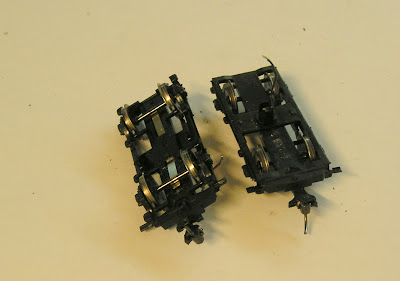
The photo above illustrates the problem. I stared at it for some while. Thought about, and started working on, a mod. to the coupling mount to take a Kadee. However, I decided in the end that it wouldn't do. Reluctantly, I decided to do away with the coupling extension cam and to mount a #20 Kadee directly on the bogie.
Bogies do pull out with a firm tug. The first thing to be noticed is the wire for the interior lighting. This should be pulled out and cut at the heat shrink covered splice. (In one case the wire inside was tangled and pulling on the wire broke it. I had to remove the body (easy enough to do) to access the wire inside and bring it out through the bogie pivot hole.
I checked the back to back measurement with a DCC Concepts gauge and, to my surprise, this seemed correct.
Next undo two screws attaching the keeper plate for the coupling extension. Remove and discard the coupling extension. Re attach the keeper plate (it doesn't do anything now).
To the bogie next. Remove the front axle. (Note that there is one un-insulated wheel on each axle, so when removing these pay attention to this when re-installing).
I built up the front of the bogie with plastic strip in order to take a screw and position the Kadee at the correct height and distance.
1) Cut a piece of 0.040" strip to length to fit over the front of the bogie. The plastic used for the bogie is impervious to plastic solvent so I use a pin and superglue method.
2) Drill two holes in the strip for 0.032" wire.
3) Drill two holes in the front of the bogie at the same locations (it's a good idea to use the strip just drilled as a jig).
4) Take a 0.100" x 0.125" piece of strip cut to the same length as 1) above. I beveled mine to make them look a bit neater.
5) Insert two shortish pieces of brass wire into the holes in the bogie, securing with superglue.
6) Cut a piece of strip about 10mm long.
7) Now, push the strip in 4) over the brass wire and secure with plastic solvent.
8) Glue the strip in 6) to the center of the assembly.
You should have something that looks like this:
The photo shows the bottom and top of the bogie.
Next, drill a hole directly adjacent to the center piece of strip. The size of hole will depend on the kind of fixing you use. Any screw with sufficient will do. The Kadee Delrin screw is convenient and you can tap for this using the Kadee tool.
Drill your #20 Kadee just ahead of where the split tails end. Cut these off.
Secure the Kadee. I like to add some superglue to the fixing to prevent loosening.
The Kadee fitted bogie looks like this:
The only question mark will be distance from bogie center. I chose this such the the knuckle hinge is about even with the buffer head.
Remove the V shaped plate inside of the buffer beam to ensure that bogie swing is not restricted.
You will have to splice the wires together and stuff them into the body.
When all is done the coaches look like this:
I'm also fitting working gangways.
18 June 2012
A quick update on progress. I've had a couple of test sessions. There is one spot on the circuit where a couple of cars have derailed, at different times. It looked to me as though there was something snagging the bogie as it exited a curve. On examination there seemed to be a potential foul between the rear of the bogie and the trussing. I scraped down the back of the trusses so that there is a bevel there now. Yesterday's session revealed just one car with a tendency to derail at the same spot. I have used my Dremel to grind down the top front of the built up plastic card on the bogie to give a bevel and more clearance. I also rounded over the rear of the bogies slightly. Finally, I also snipped off the top of the clip that holds the glazing. I'll do another test on Wednesday.


No comments:
Post a Comment